 |
Electronic Components Datasheet Search |
|
|
Electronic Components Datasheet Search |
|
The question interval is too short.
Please try again in a few seconds.

Hello, Please ask a question about SVB-29-R/K Datasheet
# Example questions:
➢ Describe the function of the '/e' option and how it impacts the schematic circuitry and connection diagram.
➢ What input current ranges are supported by the svb module, and how does the 'rem' model relate to these ranges?
➢ What are the mounting considerations for the svb module to ensure proper operation and spacing between units?
| Part No. | SVB-29-R/K |
| Manufacturer | MSYSTEM |
| Size | 111 Kbytes |
| Pages | 3 pages |
| Description | Plug-in Signal Conditioners M-UNIT |

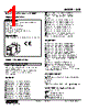


Overall Purpose:
This document describes the SVB series of signal converters/isolators, providing technical specifications, connection details, and dimensions. These devices likely take a signal (voltage or current), condition it (isolate, amplify, convert), and output a processed signal.
Key Sections and What They Mean:
1. General Information (At the Top):
- Voltage/Current Input: It accepts voltage or current signals.
- Isolation: Isolation protects the connected system from electrical noise and ground loops, enhancing safety and reliability.
- Low Drift Output: This minimizes errors in the output signal due to internal component variations, crucial for accurate measurements.
2. Technical Specifications: (Not fully listed here, but typically includes things like):
- Input Range: The range of signals the device can accept.
- Output Range: The range of signals the device produces.
- Isolation Voltage: The voltage the device can withstand between input and output.
- Accuracy: How close the output signal is to the actual input signal.
- Response Time: How quickly the device reacts to changes in the input signal.
- Operating Temperature: The range of temperatures the device can function within.
3. Ordering Information (Not detailed here, but lists the different model options available.)
4. Connection Diagrams & Terminal Assignments: (This is a significant portion of the document.)
- Terminal Numbers: Each connection point is identified with a number (1-8).
- Input Shunt Resistor: This is crucial for current input. The resistor allows the device to measure the current flowing into the input.
- Power Connections: The power supply connections for the device itself.
- Input/Output Connections: How to connect the input signal and retrieve the conditioned output signal.
- Option /E: It looks like this is an option regarding the presence of the "isolation" function.
5. Dimensional Drawings: (At the very end)
- Provides the physical dimensions of the device for proper mounting and integration. It shows physical dimensions with mounting hole locations.
Critical Points & Potential Gotchas:
️· Current Input: If you're using a current input, you *must* use the internal shunt resistor. The datasheet clearly states "*Input shunt resistor attached for current input*." Without it, the device won't correctly measure the current.
️· Option /E: Pay close attention to whether or not you need the isolation function and if the /E option is required.
️· Terminal Numbers are Key: Carefully note the terminal numbers for proper wiring. Incorrect wiring can damage the device or connected equipment.
️· Mounting: The datasheet provides mounting hole locations.
How to Use This Document:
1. Identify the Specific Model: Find the exact SVB model you're using (typically listed on the device itself).
2. Determine Input Type: Decide whether you're using a voltage or current input.
3. Wiring: Carefully follow the connection diagrams and terminal assignments to wire the device correctly.
4. Physical Mounting: Use the dimensional drawings to ensure the device fits properly in your application.
Overall Purpose:
This document describes the SVB series of signal converters/isolators, providing technical specifications, connection details, and dimensions. These devices likely take a signal (voltage or current), condition it (isolate, amplify, convert), and output a processed signal.
Key Sections and What They Mean:
1. General Information (At the Top):
- Voltage/Current Input: It accepts voltage or current signals.
- Isolation: Isolation protects the connected system from electrical noise and ground loops, enhancing safety and reliability.
- Low Drift Output: This minimizes errors in the output signal due to internal component variations, crucial for accurate measurements.
2. Technical Specifications: (Not fully listed here, but typically includes things like):
- Input Range: The range of signals the device can accept.
- Output Range: The range of signals the device produces.
- Isolation Voltage: The voltage the device can withstand between input and output.
- Accuracy: How close the output signal is to the actual input signal.
- Response Time: How quickly the device reacts to changes in the input signal.
- Operating Temperature: The range of temperatures the device can function within.
3. Ordering Information (Not detailed here, but lists the different model options available.)
4. Connection Diagrams & Terminal Assignments: (This is a significant portion of the document.)
- Terminal Numbers: Each connection point is identified with a number (1-8).
- Input Shunt Resistor: This is crucial for current input. The resistor allows the device to measure the current flowing into the input.
- Power Connections: The power supply connections for the device itself.
- Input/Output Connections: How to connect the input signal and retrieve the conditioned output signal.
- Option /E: It looks like this is an option regarding the presence of the "isolation" function.
5. Dimensional Drawings: (At the very end)
- Provides the physical dimensions of the device for proper mounting and integration. It shows physical dimensions with mounting hole locations.
Critical Points & Potential Gotchas:
️· Current Input: If you're using a current input, you *must* use the internal shunt resistor. The datasheet clearly states "*Input shunt resistor attached for current input*." Without it, the device won't correctly measure the current.
️· Option /E: Pay close attention to whether or not you need the isolation function and if the /E option is required.
️· Terminal Numbers are Key: Carefully note the terminal numbers for proper wiring. Incorrect wiring can damage the device or connected equipment.
️· Mounting: The datasheet provides mounting hole locations.
How to Use This Document:
1. Identify the Specific Model: Find the exact SVB model you're using (typically listed on the device itself).
2. Determine Input Type: Decide whether you're using a voltage or current input.
3. Wiring: Carefully follow the connection diagrams and terminal assignments to wire the device correctly.
4. Physical Mounting: Use the dimensional drawings to ensure the device fits properly in your application.
| Part No. | SVB-29-R/K |
| Manufacturer | MSYSTEM |
| Size | 111 Kbytes |
| Pages | 3 pages |
| Description | Plug-in Signal Conditioners M-UNIT |
| Does ALLDATASHEET help your business so far? [ DONATE ] |
About Alldatasheet | Advertisement | Contact us | Privacy Policy | Link to Datasheet | Link Exchange | Manufacturer List All Rights Reserved©Alldatasheet.com |
| Russian : Alldatasheetru.com | Korean : Alldatasheet.co.kr | Spanish : Alldatasheet.es | French : Alldatasheet.fr | Italian : Alldatasheetit.com Portuguese : Alldatasheetpt.com | Polish : Alldatasheet.pl | Vietnamese : Alldatasheet.vn Indian : Alldatasheet.in | Mexican : Alldatasheet.com.mx | British : Alldatasheet.co.uk | New Zealand : Alldatasheet.co.nz |
|
Family Site : ic2ic.com |
icmetro.com |
 Indian ▼
  English
 Chinese
 German
 Japanese
 Russian
 Korean
 Spanish
 French
 Italian
 Portuguese
 Polish
 Vietnamese
 Mexican
 British
 New Zealand