 |
Electronic Components Datasheet Search |
|
|
Electronic Components Datasheet Search |
|
The question interval is too short.
Please try again in a few seconds.

Hello, Please ask a question about WJM-10Z-R Datasheet
# Example questions:
➢ What type of signal (voltage or current) is output 1?
➢ What are the available output current options for output 1, and what is the voltage input required for the device?
➢ If a user needs to connect multiple wjm modules side-by-side, is any additional spacing required between them?
| Part No. | WJM-10Z-R |
| Manufacturer | MSYSTEM |
| Size | 101 Kbytes |
| Pages | 3 pages |
| Description | Dual Output Plug-in Signal Conditioners W-UNIT |

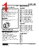
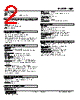

1. General Description & Purpose:
️· What it is: A configurable I/O module. This means it can be used for various input and output functions, and its behavior can be adjusted based on the specific application.
️· Function: Likely a component in a Programmable Logic Controller (PLC) or similar industrial control system. It allows interfacing between the control system and the real-world processes it manages (sensors, actuators, etc.).
2. Configuration Options (Key to Flexibility):
️· Configurability: The module's functionality is likely programmed via software or DIP switches, enabling a wide range of I/O types.
️· Specific I/O Types:
- Inputs: The datasheet doesn't explicitly list input *types*, but given the outputs, likely supports digital inputs (on/off signals), and potentially analog inputs (voltage or current signals).
- Outputs: The datasheet highlights different outputs.
■ Voltage Outputs Voltage output signal can be selected, the exact range is not specified.
■ Current Outputs: Supports current output, the exact range is not specified.
3. Electrical Specifications:
️· Power Supply: The voltage requirement for the module is not explicitly stated, but it is most likely DC.
️· Output Signals: The details about output signal are vague but can be selected, the exact specifications are not provided.
️· Input/Output Ranges The exact input and output ranges are not specified, and require further documentation.
4. Mechanical Details & Mounting:
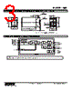
️· Dimensions: The datasheet includes a schematic diagram depicting its physical layout and dimensions (approx. 107mm x 50mm x 3.3mm - roughly 4.21" x 1.97" x 0.13").
️· Mounting: Designed for DIN rail mounting, a standard in industrial automation. "No extra space needed between units" suggests a compact design for dense panel installations.
️· Terminal Connections: Provides clear labeling for terminal connections (e.g. V+, V-, I+, I-).
5. Important Notes & Considerations (based on the provided information):
️· Further Documentation: The datasheet is limited. More detailed specifications on input/output ranges, configuration methods (software, DIP switches), and specific signal types would be crucial for proper integration.
️· Compatibility: Ensure the module's electrical characteristics (voltage, current) are compatible with the PLC or control system it will be used with.
️· Safety: Implement appropriate safety measures when integrating this module into an industrial control system.
To fully understand how to use this module, you would need the following additional information:
️· Configuration Guide: How to configure the module for specific input/output types.
️· Electrical Characteristics Table: Detailed specifications for input voltage ranges, output current/voltage limits, and signal types.
️· Software/Programming Information: How to interface with the module via software.
1. General Description & Purpose:
️· What it is: A configurable I/O module. This means it can be used for various input and output functions, and its behavior can be adjusted based on the specific application.
️· Function: Likely a component in a Programmable Logic Controller (PLC) or similar industrial control system. It allows interfacing between the control system and the real-world processes it manages (sensors, actuators, etc.).
2. Configuration Options (Key to Flexibility):
️· Configurability: The module's functionality is likely programmed via software or DIP switches, enabling a wide range of I/O types.
️· Specific I/O Types:
- Inputs: The datasheet doesn't explicitly list input *types*, but given the outputs, likely supports digital inputs (on/off signals), and potentially analog inputs (voltage or current signals).
- Outputs: The datasheet highlights different outputs.
■ Voltage Outputs Voltage output signal can be selected, the exact range is not specified.
■ Current Outputs: Supports current output, the exact range is not specified.
3. Electrical Specifications:
️· Power Supply: The voltage requirement for the module is not explicitly stated, but it is most likely DC.
️· Output Signals: The details about output signal are vague but can be selected, the exact specifications are not provided.
️· Input/Output Ranges The exact input and output ranges are not specified, and require further documentation.
4. Mechanical Details & Mounting:
️· Dimensions: The datasheet includes a schematic diagram depicting its physical layout and dimensions (approx. 107mm x 50mm x 3.3mm - roughly 4.21" x 1.97" x 0.13").
️· Mounting: Designed for DIN rail mounting, a standard in industrial automation. "No extra space needed between units" suggests a compact design for dense panel installations.
️· Terminal Connections: Provides clear labeling for terminal connections (e.g. V+, V-, I+, I-).
5. Important Notes & Considerations (based on the provided information):
️· Further Documentation: The datasheet is limited. More detailed specifications on input/output ranges, configuration methods (software, DIP switches), and specific signal types would be crucial for proper integration.
️· Compatibility: Ensure the module's electrical characteristics (voltage, current) are compatible with the PLC or control system it will be used with.
️· Safety: Implement appropriate safety measures when integrating this module into an industrial control system.
To fully understand how to use this module, you would need the following additional information:
️· Configuration Guide: How to configure the module for specific input/output types.
️· Electrical Characteristics Table: Detailed specifications for input voltage ranges, output current/voltage limits, and signal types.
️· Software/Programming Information: How to interface with the module via software.
| Part No. | WJM-10Z-R |
| Manufacturer | MSYSTEM |
| Size | 101 Kbytes |
| Pages | 3 pages |
| Description | Dual Output Plug-in Signal Conditioners W-UNIT |
| Does ALLDATASHEET help your business so far? [ DONATE ] |
About Alldatasheet | Advertisement | Contact us | Privacy Policy | Link to Datasheet | Link Exchange | Manufacturer List All Rights Reserved©Alldatasheet.com |
| Russian : Alldatasheetru.com | Korean : Alldatasheet.co.kr | Spanish : Alldatasheet.es | French : Alldatasheet.fr | Italian : Alldatasheetit.com Portuguese : Alldatasheetpt.com | Polish : Alldatasheet.pl | Vietnamese : Alldatasheet.vn Indian : Alldatasheet.in | Mexican : Alldatasheet.com.mx | British : Alldatasheet.co.uk | New Zealand : Alldatasheet.co.nz |
|
Family Site : ic2ic.com |
icmetro.com |
 Indian ▼
  English
 Chinese
 German
 Japanese
 Russian
 Korean
 Spanish
 French
 Italian
 Portuguese
 Polish
 Vietnamese
 Mexican
 British
 New Zealand