 |
Electronic Components Datasheet Search |
|
|
Electronic Components Datasheet Search |
|
The question interval is too short.
Please try again in a few seconds.

Hello, Please ask a question about ALPT-133-R Datasheet
# Example questions:
➢ What components are suggested for protecting the load coil in an inductive circuit?
➢ What is indicated by the note 'relay status for output codes “1” & “4”, at power off.'?
➢ What does 'u(+)' and 'v(-)' likely represent in the context of these diagrams?
| Part No. | ALPT-133-R |
| Manufacturer | MSYSTEM |
| Size | 126 Kbytes |
| Pages | 4 pages |
| Description | Limit Alarms (rotary switch adj.) AL-UNIT |

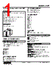
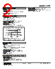
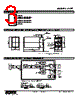

Okay, I've analyzed the text provided. Here's a breakdown of the information and an attempt to extract the most relevant parts, organized for clarity.
1. Overall Context:
️· This is a snippet from a technical document, likely related to a product (identified as "ALPT") from M-System (as indicated by the URL at the bottom).
️· The document is version 9 of ES-2738, spanning pages 3 and 4.
️· It describes relay protection aspects of the ALPT device.
2. Key Components & Systems (based on the content):
️· ALPT: The core product.
️· Relays: An integral part of the device, used for output control, specifically regarding output codes "1" & "4" when the power is OFF.
️· Power Supply: The device can operate on either AC or DC power.
️· Inductive Load: The relay is used to control inductive loads, such as coils.
️· Protection Components: Includes diodes, varistors, or CR circuits for protection of the relay against voltage spikes or reverse voltage.
️· U(+), V(–): These likely denote voltage polarity connections.
3. Critical Information – Relay Status at Power OFF:
️· The most significant piece of information is the statement: "Relay status for output codes “1” & “4”, at power OFF." This indicates a defined behavior for these outputs when the device is unpowered.
️· The rest of the text surrounding this statement seems to be describing the circuit and components used to achieve this relay status.
4. Circuit Description (based on the diagrams):
️· AC-Powered Circuit: Includes a diode (presumably to block reverse voltage).
️· DC-Powered Circuit: Also includes a diode, suggesting similar reverse voltage protection.
️· The `Load (Coil)` section of the circuit diagram indicates that the relay is being used to control an inductive coil.
5. Summary:
The document describes a system where relays control inductive loads. The key design feature is the defined state of relays 1 & 4 when power is off, controlled with protection circuits (diodes). The device supports both AC and DC power operation with similar protective measures.
In short, you can use this information to:
️· Understand the functionality of the ALPT device.
️· Troubleshoot relay issues, especially related to power-off behavior.
️· Design safe and reliable circuits using the ALPT product.
1. Overall Context:
️· This is a snippet from a technical document, likely related to a product (identified as "ALPT") from M-System (as indicated by the URL at the bottom).
️· The document is version 9 of ES-2738, spanning pages 3 and 4.
️· It describes relay protection aspects of the ALPT device.
2. Key Components & Systems (based on the content):
️· ALPT: The core product.
️· Relays: An integral part of the device, used for output control, specifically regarding output codes "1" & "4" when the power is OFF.
️· Power Supply: The device can operate on either AC or DC power.
️· Inductive Load: The relay is used to control inductive loads, such as coils.
️· Protection Components: Includes diodes, varistors, or CR circuits for protection of the relay against voltage spikes or reverse voltage.
️· U(+), V(–): These likely denote voltage polarity connections.
3. Critical Information – Relay Status at Power OFF:
️· The most significant piece of information is the statement: "Relay status for output codes “1” & “4”, at power OFF." This indicates a defined behavior for these outputs when the device is unpowered.
️· The rest of the text surrounding this statement seems to be describing the circuit and components used to achieve this relay status.
4. Circuit Description (based on the diagrams):
️· AC-Powered Circuit: Includes a diode (presumably to block reverse voltage).
️· DC-Powered Circuit: Also includes a diode, suggesting similar reverse voltage protection.
️· The `Load (Coil)` section of the circuit diagram indicates that the relay is being used to control an inductive coil.
5. Summary:
The document describes a system where relays control inductive loads. The key design feature is the defined state of relays 1 & 4 when power is off, controlled with protection circuits (diodes). The device supports both AC and DC power operation with similar protective measures.
In short, you can use this information to:
️· Understand the functionality of the ALPT device.
️· Troubleshoot relay issues, especially related to power-off behavior.
️· Design safe and reliable circuits using the ALPT product.
| Part No. | ALPT-133-R |
| Manufacturer | MSYSTEM |
| Size | 126 Kbytes |
| Pages | 4 pages |
| Description | Limit Alarms (rotary switch adj.) AL-UNIT |
| Does ALLDATASHEET help your business so far? [ DONATE ] |
About Alldatasheet | Advertisement | Contact us | Privacy Policy | Link to Datasheet | Link Exchange | Manufacturer List All Rights Reserved©Alldatasheet.com |
| Russian : Alldatasheetru.com | Korean : Alldatasheet.co.kr | Spanish : Alldatasheet.es | French : Alldatasheet.fr | Italian : Alldatasheetit.com Portuguese : Alldatasheetpt.com | Polish : Alldatasheet.pl | Vietnamese : Alldatasheet.vn Indian : Alldatasheet.in | Mexican : Alldatasheet.com.mx | British : Alldatasheet.co.uk | New Zealand : Alldatasheet.co.nz |
|
Family Site : ic2ic.com |
icmetro.com |
 Indian ▼
  English
 Chinese
 German
 Japanese
 Russian
 Korean
 Spanish
 French
 Italian
 Portuguese
 Polish
 Vietnamese
 Mexican
 British
 New Zealand