 |
Electronic Components Datasheet Search |
|
|
Electronic Components Datasheet Search |
|
The question interval is too short.
Please try again in a few seconds.

Hello, Please ask a question about APTA-133-R Datasheet
# Example questions:
➢ What are the available input voltage options for the apta device, as implied by the connection diagrams?
➢ What type of mounting is suggested for the apta units to minimize space requirements?
➢ What protective measure is recommended when using the apta with inductive loads?
| Part No. | APTA-133-R |
| Manufacturer | MSYSTEM |
| Size | 125 Kbytes |
| Pages | 4 pages |
| Description | Limit Alarms (potentiometer adj.) A-UNIT |

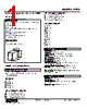

1. General Information & Purpose
️· Product: APTA (likely a process or signal monitor – the specifics aren't fully defined)
️· Function: The APTA appears to monitor a process or signal, triggering relays (outputs) based on the measured value. It acts as a comparator.
️· Manufacturer: M-System
2. Power Requirements:
️· AC Powered: Voltage not specified.
️· DC Powered: Voltage not specified.
3. Input & Output
️· Input: The signal being monitored is connected to "U(+)" and "V(-)" terminals. The exact nature of the signal (voltage, current, etc.) isn't explicitly defined.
️· Output: Relay contacts are used as the output. The state of the relays depends on the input signal's comparison to a setpoint.
- `*`Relay status for output codes “1” & “4”, at power OFF.
4. Relay Protection (Crucial for Proper Use)
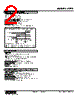
️· AC and DC Powered: When using inductive loads (like motors, solenoids, or relays) connected to the APTA's relay contacts, *external protection is MANDATORY*.
️· Protection Method: A varistor or spark-quenching circuit must be placed *in parallel* with the inductive load. This protects the APTA’s relay contacts from damage caused by voltage spikes when the inductive load is switched off.
5. Mounting
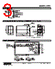
️· Units can be mounted close together - no extra space needed.
6. Input Signal Configuration (Schematic)
️· The schematic depicts a source connected to "U(+)" and "V(-)"
️· It shows a connection between these terminals and an input signal.
7. Relay Operation & Output Codes:
️· Output Codes: Output codes "1" and "4" have relays that are de-energized (OFF) when power is initially applied to the APTA.
️· This implies specific functionalities associated with each output code.
8. Key Diagrams/Tables & Their Significance
️· Schematic Circuitry & Connection Diagram: This is crucial for understanding how to connect the APTA correctly, particularly regarding the "U(+)" and "V(-)" input signal and the relay output.
️· Relay Protection Diagram: Highlights the absolute necessity of varistor or spark quenching circuits when connecting inductive loads to the APTA's relay contacts. Ignoring this can damage the APTA.
1. General Information & Purpose
️· Product: APTA (likely a process or signal monitor – the specifics aren't fully defined)
️· Function: The APTA appears to monitor a process or signal, triggering relays (outputs) based on the measured value. It acts as a comparator.
️· Manufacturer: M-System
2. Power Requirements:
️· AC Powered: Voltage not specified.
️· DC Powered: Voltage not specified.
3. Input & Output
️· Input: The signal being monitored is connected to "U(+)" and "V(-)" terminals. The exact nature of the signal (voltage, current, etc.) isn't explicitly defined.
️· Output: Relay contacts are used as the output. The state of the relays depends on the input signal's comparison to a setpoint.
- `*`Relay status for output codes “1” & “4”, at power OFF.
4. Relay Protection (Crucial for Proper Use)
️· AC and DC Powered: When using inductive loads (like motors, solenoids, or relays) connected to the APTA's relay contacts, *external protection is MANDATORY*.
️· Protection Method: A varistor or spark-quenching circuit must be placed *in parallel* with the inductive load. This protects the APTA’s relay contacts from damage caused by voltage spikes when the inductive load is switched off.
5. Mounting
️· Units can be mounted close together - no extra space needed.
6. Input Signal Configuration (Schematic)
️· The schematic depicts a source connected to "U(+)" and "V(-)"
️· It shows a connection between these terminals and an input signal.
7. Relay Operation & Output Codes:
️· Output Codes: Output codes "1" and "4" have relays that are de-energized (OFF) when power is initially applied to the APTA.
️· This implies specific functionalities associated with each output code.
8. Key Diagrams/Tables & Their Significance
️· Schematic Circuitry & Connection Diagram: This is crucial for understanding how to connect the APTA correctly, particularly regarding the "U(+)" and "V(-)" input signal and the relay output.
️· Relay Protection Diagram: Highlights the absolute necessity of varistor or spark quenching circuits when connecting inductive loads to the APTA's relay contacts. Ignoring this can damage the APTA.
| Part No. | APTA-133-R |
| Manufacturer | MSYSTEM |
| Size | 125 Kbytes |
| Pages | 4 pages |
| Description | Limit Alarms (potentiometer adj.) A-UNIT |
| Does ALLDATASHEET help your business so far? [ DONATE ] |
About Alldatasheet | Advertisement | Contact us | Privacy Policy | Link to Datasheet | Link Exchange | Manufacturer List All Rights Reserved©Alldatasheet.com |
| Russian : Alldatasheetru.com | Korean : Alldatasheet.co.kr | Spanish : Alldatasheet.es | French : Alldatasheet.fr | Italian : Alldatasheetit.com Portuguese : Alldatasheetpt.com | Polish : Alldatasheet.pl | Vietnamese : Alldatasheet.vn Indian : Alldatasheet.in | Mexican : Alldatasheet.com.mx | British : Alldatasheet.co.uk | New Zealand : Alldatasheet.co.nz |
|
Family Site : ic2ic.com |
icmetro.com |
 Indian ▼
  English
 Chinese
 German
 Japanese
 Russian
 Korean
 Spanish
 French
 Italian
 Portuguese
 Polish
 Vietnamese
 Mexican
 British
 New Zealand