|
Electronic Components Datasheet Search |
|
|
Electronic Components Datasheet Search |
|
AM6548BACDXEAF Datasheet(PDF) 157 Page - Texas Instruments |
|
|
|
|||||||||||||||||||||||||||||
AM6548BACDXEAF Datasheet(HTML) 157 Page - Texas Instruments |
|
|
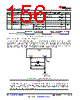
157 / 282 page  CL= C C f1 2 f (C +C ) f1 f2 SPRS932_CLOCK_03 Figure 7-20. Load Capacitance Equation The crystal must be in the fundamental mode of operation and parallel resonant. Table 7-18 summarizes the required electrical constraints. Table 7-18. OSC1 Crystal Electrical Characteristics NAME DESCRIPTION MIN TYP MAX UNIT fp Parallel resonance crystal frequency 19.2, 20, 24, 25, 26, 27 MHz Cf1 Cf1 load capacitance for crystal parallel resonance with Cf1 = Cf2 12 24 pF Cf2 Cf2 load capacitance for crystal parallel resonance with Cf1 = Cf2 12 24 pF ESR(Cf1,Cf2) Crystal ESR 100 Ω CO Crystal shunt capacitance ESR = 30 Ω ESR = 40 Ω 19.2 MHz, 20 MHz, 24 MHz, 25 MHz, 26 MHz, 27 MHz 7 pF ESR = 50 Ω 19.2 MHz, 20 MHz 7 pF 24 MHz, 25 MHz, 26 MHz, 27 MHz 5 pF ESR = 60 Ω 19.2 MHz, 20 MHz 7 pF 24 MHz, 25 MHz, 26 MHz, 27 MHz Not Supported - ESR = 80 Ω 19.2 MHz, 20 MHz 5 pF 24 MHz, 25 MHz, 26 MHz, 27 MHz Not Supported - ESR = 100 Ω 19.2 MHz, 20 MHz 3 pF 24 MHz, 25 MHz, 26 MHz, 27 MHz Not Supported - LM Crystal motional inductance for fp = 20 MHz 10.16 mH CM Crystal motional capacitance 3.42 fF fj(OSC1_XI) Frequency accuracy, OSC1_XI Ethernet RGMII and RMII not used ±100 ppm Ethernet RGMII and RMII using derived clock ±50 When selecting a crystal, the system design must consider the temperature and aging characteristics of a based on the worst case environment and expected life expectancy of the system. Table 7-19 details the switching characteristics of the oscillator and the requirements of the input clock. Table 7-19. OSC1 Switching Characteristics – Crystal Mode NAME DESCRIPTION MIN TYP MAX UNIT fp Oscillation frequency 19.2, 20, 24, 25, 26, 27 MHz tsX Start-up time 2(1) ms (1) In order to meet the start-up time defined in this table, the crystal needs to be selected according to the following equation: Tsu = K×Lm/ (Ro-ESR) + Δt where Lm is crystal motional inductance, RO is the negative resistance of amplifier, ESR is the crystal Effective series resistance and K is a constant which represents the initial conditions. Δt is the time amplifier takes to reach its bias point after power down is released. www.ti.com AM6548, AM6528, AM6526 SPRSP52B – DECEMBER 2019 – REVISED JUNE 2021 Copyright © 2021 Texas Instruments Incorporated Submit Document Feedback 157 Product Folder Links: AM6548 AM6528 AM6526 |
|
Link URL |
| Does ALLDATASHEET help your business so far? [ DONATE ] |
About Alldatasheet | Advertisement | Contact us | Privacy Policy | Link to Datasheet | Link Exchange | Manufacturer List All Rights Reserved©Alldatasheet.com |
| Russian : Alldatasheetru.com | Korean : Alldatasheet.co.kr | Spanish : Alldatasheet.es | French : Alldatasheet.fr | Italian : Alldatasheetit.com Portuguese : Alldatasheetpt.com | Polish : Alldatasheet.pl | Vietnamese : Alldatasheet.vn Indian : Alldatasheet.in | Mexican : Alldatasheet.com.mx | British : Alldatasheet.co.uk | New Zealand : Alldatasheet.co.nz |
|
Family Site : ic2ic.com |
icmetro.com |
 Indian ▼
 English
 Chinese
 German
 Japanese
 Russian
 Korean
 Spanish
 French
 Italian
 Portuguese
 Polish
 Vietnamese
 Indian
 Mexican
 British
 New Zealand