 |
Electronic Components Datasheet Search |
|
|
Electronic Components Datasheet Search |
|
The question interval is too short.
Please try again in a few seconds.

Hello, Please ask a question about 34AA02-I/P Datasheet
# Example questions:
➢ What is the primary function of the vcc threshold detector circuit within the 34xx02?
➢ Describe how the chip select bits (a2, a1, a0) can be utilized to expand the memory address space when using multiple 34xx02 devices on the same bus.
➢ Explain the difference between a 'byte write' and a 'page write' operation in terms of how data is written to the 34xx02’s memory.
| Part No. | 34AA02-I/P |
| Manufacturer | MICROCHIP |
| Size | 631 Kbytes |
| Pages | 32 pages |
| Description | 2K I2C Serial EEPROM Software Write-Protect |

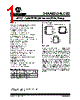


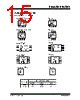


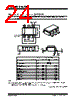



Okay, here's a summary of the information from the provided text, broken down into key points. I'm aiming for clarity and conciseness, organized by the main topics covered.
1. Device Overview & Purpose:
️· Chip Family: The document describes the 34XX02 family of EEPROM devices (likely serial EEPROMs) designed for use with I2C communication.
️· Function: They serve as non-volatile memory storage.
2. Communication Protocol (I2C):
️· Protocol: The devices communicate using the I2C (Inter-Integrated Circuit) protocol.
️· Addressing: Each device has a unique address, selectable via Chip Select pins (A2, A1, A0). Up to 8 devices can share the same bus.
️· Read/Write Control: The 8th bit in the slave address byte determines if the operation is a Read (1) or a Write (0).
3. Write Operations:
️· Byte Write: Writing a single byte to a specific address. Requires sending a control byte, word address, and data byte.
️· Page Write: Writing a block of data (up to 16 bytes) into a page in memory. Faster than byte-by-byte writing.
️· Write Cycle Time: A critical parameter that must be observed during writes.
️· Acknowledge Polling: A technique to determine when a write cycle is complete, improving bus throughput.
4. Read Operations:
️· Current Address Read: Reading the data at the address of the last operation (write or read).
️· Random Read: Reading data at a specific, pre-defined address.
️· Sequential Read: Reading data sequentially, allowing the entire memory to be read in one operation.
️· Expanding Address Space: Chip Select bits can be used to expand the contiguous address space.
5. Key Features & Protections:
️· VCC Threshold Detection: Disables write logic if the supply voltage (VCC) falls below a safe level.
️· Schmitt Trigger Inputs: Provide noise immunity for SCL and SDA lines.
️· Brown-Out Protection: Protects against data loss in cases of power fluctuations.
6. Important Tables & Figures:
️· Control Byte Allocation Table: Defines the role of control code, chip select bits, and the R/W bit.
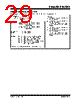
️· Flow Diagrams/Figures: Illustrate Byte Write, Page Write, Random Read, Sequential Read, and Acknowledge Polling processes.
In essence, the document provides a technical guide to using the 34XX02 EEPROM devices, detailing their operation, addressing scheme, write and read procedures, and protective features within an I2C communication environment.
1. Device Overview & Purpose:
️· Chip Family: The document describes the 34XX02 family of EEPROM devices (likely serial EEPROMs) designed for use with I2C communication.
️· Function: They serve as non-volatile memory storage.
2. Communication Protocol (I2C):
️· Protocol: The devices communicate using the I2C (Inter-Integrated Circuit) protocol.
️· Addressing: Each device has a unique address, selectable via Chip Select pins (A2, A1, A0). Up to 8 devices can share the same bus.
️· Read/Write Control: The 8th bit in the slave address byte determines if the operation is a Read (1) or a Write (0).
3. Write Operations:
️· Byte Write: Writing a single byte to a specific address. Requires sending a control byte, word address, and data byte.
️· Page Write: Writing a block of data (up to 16 bytes) into a page in memory. Faster than byte-by-byte writing.
️· Write Cycle Time: A critical parameter that must be observed during writes.
️· Acknowledge Polling: A technique to determine when a write cycle is complete, improving bus throughput.
4. Read Operations:
️· Current Address Read: Reading the data at the address of the last operation (write or read).
️· Random Read: Reading data at a specific, pre-defined address.
️· Sequential Read: Reading data sequentially, allowing the entire memory to be read in one operation.
️· Expanding Address Space: Chip Select bits can be used to expand the contiguous address space.
5. Key Features & Protections:
️· VCC Threshold Detection: Disables write logic if the supply voltage (VCC) falls below a safe level.
️· Schmitt Trigger Inputs: Provide noise immunity for SCL and SDA lines.
️· Brown-Out Protection: Protects against data loss in cases of power fluctuations.
6. Important Tables & Figures:
️· Control Byte Allocation Table: Defines the role of control code, chip select bits, and the R/W bit.
️· Flow Diagrams/Figures: Illustrate Byte Write, Page Write, Random Read, Sequential Read, and Acknowledge Polling processes.
In essence, the document provides a technical guide to using the 34XX02 EEPROM devices, detailing their operation, addressing scheme, write and read procedures, and protective features within an I2C communication environment.
| Part No. | 34AA02-I/P |
| Manufacturer | MICROCHIP |
| Size | 631 Kbytes |
| Pages | 32 pages |
| Description | 2K I2C Serial EEPROM Software Write-Protect |
| Does ALLDATASHEET help your business so far? [ DONATE ] |
About Alldatasheet | Advertisement | Contact us | Privacy Policy | Link to Datasheet | Link Exchange | Manufacturer List All Rights Reserved©Alldatasheet.com |
| Russian : Alldatasheetru.com | Korean : Alldatasheet.co.kr | Spanish : Alldatasheet.es | French : Alldatasheet.fr | Italian : Alldatasheetit.com Portuguese : Alldatasheetpt.com | Polish : Alldatasheet.pl | Vietnamese : Alldatasheet.vn Indian : Alldatasheet.in | Mexican : Alldatasheet.com.mx | British : Alldatasheet.co.uk | New Zealand : Alldatasheet.co.nz |
|
Family Site : ic2ic.com |
icmetro.com |
 Indian ▼
  English
 Chinese
 German
 Japanese
 Russian
 Korean
 Spanish
 French
 Italian
 Portuguese
 Polish
 Vietnamese
 Mexican
 British
 New Zealand