 |
Electronic Components Datasheet Search |
|
|
Electronic Components Datasheet Search |
|
R3-AV4S/CE Datasheet(PDF) 2 Page - M-System Co.,Ltd. |
|
|
|||||||||||||||||||||||||||||
R3-AV4S/CE Datasheet(HTML) 2 Page - M-System Co.,Ltd. |
|
|
2 / 4 page 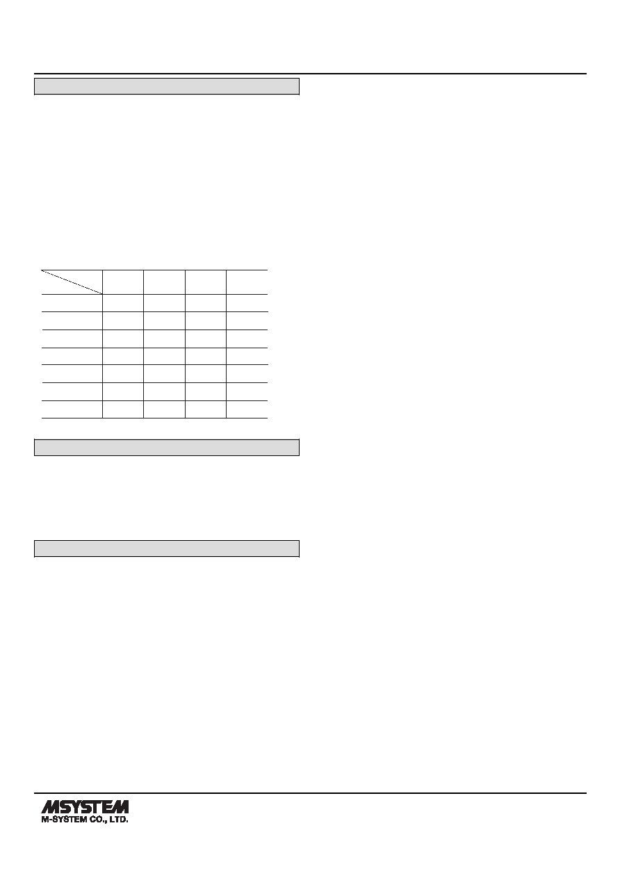 MODEL: R3-AV4 R3-AV4 SPECIFICATIONS ES-8435 Rev.7 Page 2/4 https://www.m-system.co.jp/ PERFORMANCE Conversion accuracy: Refer to the table at the end of this section. Conversion rate: 80 / 40 / 20 / 10 msec. selectable Data allocation: 1 Current consumption: 60 mA Temp. coefficient: ±0.015 % /°C (±0.008 %/°F) (±0.03 % /°C [±0.02 %/°F] with 0 – 5 V or 1 – 5 V range) Insulation resistance: ≥ 100 MΩ with 500 V DC Dielectric strength: 1500 V AC @ 1 minute (input 1 to input 2 to input 3 to input 4 to internal bus or internal power) 2000 V AC @ 1 minute (power input to FG; isolated on the power supply module) -5 – +5 V -10 – +10 V RANGE RATE 80 msec. 40 msec. 20 msec. 10 msec. ±0.05% ±0.1% ±0.2% ±0.4% ±0.05% ±0.1% ±0.2% ±0.4% -1 – +1 V ±0.05% ±0.1% ±0.2% ±0.4% 0 – 5 V 0 – 10 V ±0.05% ±0.1% ±0.2% ±0.4% ±0.1% ±0.2% ±0.4% ±0.8% 1 – 5 V ±0.1% ±0.2% ±0.4% ±0.8% 0 – 1 V ±0.05% ±0.1% ±0.2% ±0.4% Conversion accuracy STANDARDS & APPROVALS EU conformity: EMC Directive EMI EN 61000-6-4 EMS EN 61000-6-2 RoHS Directive ALARM SETTING The following parameters are programmable using the PC Configurator Software (model: R3CON). ■ALARM TRIP POINT (-15.00 to +115.00 %; factory set to A1: 80.00, A2: 60.00, A3: 40.00, A4: 20.00) Four alarm setpoints are selectable per each input. ■ALARM TYPE (High or Low; factory set to A1: High, A2: High, A3: Low, A4: Low) High or Low alarm is selectable for each alarm trip point. High alarm: An alarm is set when the input signal goes above the setpoint. Low alarm: An alarm is set when the input signal goes below the setpoint. ■DEADBAND (HYSTERESIS) (0.00 to 100.00 %; factory set to 5.00) Deadband (deviation between the points where the alarm is set and reset) is selectable for each alarm trip point. ■ALARM ON DELAY TIME (0.0 to 99.0 seconds; factory set to 1.0) The alarm output is set when the preset time elapses after the input has entered in the alarm range. This setting is common to all four points. ■POWER ON DELAY TIME (0.0 to 99.0 sec.; factory set to 5.0) The alarm output start functioning in the preset time after the power has been turned on. This setting is common to all four points. ■ALARM HOLD TIME (0.0 to 99.0 seconds; factory set to 1.0) The alarm output is held for the preset time even if it is reset in shorter time. This setting is common to all four points. |
|
|
Link URL |
| Does ALLDATASHEET help your business so far? [ DONATE ] |
About Alldatasheet | Advertisement | Contact us | Privacy Policy | Link to Datasheet | Link Exchange | Manufacturer List All Rights Reserved©Alldatasheet.com |
| Russian : Alldatasheetru.com | Korean : Alldatasheet.co.kr | Spanish : Alldatasheet.es | French : Alldatasheet.fr | Italian : Alldatasheetit.com Portuguese : Alldatasheetpt.com | Polish : Alldatasheet.pl | Vietnamese : Alldatasheet.vn Indian : Alldatasheet.in | Mexican : Alldatasheet.com.mx | British : Alldatasheet.co.uk | New Zealand : Alldatasheet.co.nz |
|
Family Site : ic2ic.com |
icmetro.com |
 Indian ▼
 English
 Chinese
 German
 Japanese
 Russian
 Korean
 Spanish
 French
 Italian
 Portuguese
 Polish
 Vietnamese
 Indian
 Mexican
 British
 New Zealand


