|
Electronic Components Datasheet Search |
|
|
Electronic Components Datasheet Search |
|
FX643 Datasheet(PDF) 7 Page - CML Microcircuits |
|
|
|||||||||||||||||||||||||||||
FX643 Datasheet(HTML) 7 Page - CML Microcircuits |
|
|
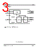
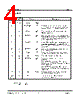
7 / 14 page  Call Progress Tone Detector FX643 © 1996 Consumer Microcircuits Limited 7 D/643/4 No Signal: A signal falling outside the nominal range 120Hz to 900Hz or Special Information Tone or the absence of an input signal. Either will be detected as a No Signal condition. Nominal: Subject to dynamic tolerances within the signal analysis process. Absolute values are not material or adverse to performance. 1.5.3 Block Diagram Description (reference Figure 1) Slicer The input signal to the slicer is amplified by a self-biased inverting amplifier. The dc bias of this input is internally set at ½VDD. Signal Analyser The frequency range, quality and consistency of the input signal is analysed by this functional block. The signal to noise ratio must be 16dB or greater. The signal must be consistent over a period of about 140 ms. These decode criteria are continuously monitored and the assessment is updated every 7 ms, reference Figure 3. The analyser samples the call progress signal at 9.3kHz; so care should be taken to avoid high frequency signals (e.g. 18kHz) aliasing into the call progress band. Control Logic This block categorises the nature of the signal into various decoded output states and controls the two output pins. See the Decode Output Truth Table in section 1.5.4. Clock An external clock source is to be connected to the XTAL/CLOCK input pin. Alternatively, the internal oscillator may be used with an external crystal if the 16-pin SOIC (D4) version of the FX643 is used. |
|
|
Link URL |
| Does ALLDATASHEET help your business so far? [ DONATE ] |
About Alldatasheet | Advertisement | Contact us | Privacy Policy | Link to Datasheet | Link Exchange | Manufacturer List All Rights Reserved©Alldatasheet.com |
| Russian : Alldatasheetru.com | Korean : Alldatasheet.co.kr | Spanish : Alldatasheet.es | French : Alldatasheet.fr | Italian : Alldatasheetit.com Portuguese : Alldatasheetpt.com | Polish : Alldatasheet.pl | Vietnamese : Alldatasheet.vn Indian : Alldatasheet.in | Mexican : Alldatasheet.com.mx | British : Alldatasheet.co.uk | New Zealand : Alldatasheet.co.nz |
|
Family Site : ic2ic.com |
icmetro.com |
 Indian ▼
 English
 Chinese
 German
 Japanese
 Russian
 Korean
 Spanish
 French
 Italian
 Portuguese
 Polish
 Vietnamese
 Indian
 Mexican
 British
 New Zealand