|
Electronic Components Datasheet Search |
|
|
Electronic Components Datasheet Search |
|
DS2114 Datasheet(PDF) 2 Page - Dallas Semiconductor |
|
|
|||||||||||||||||||||||||||||
DS2114 Datasheet(HTML) 2 Page - Dallas Semiconductor |
|
|
2 / 6 page 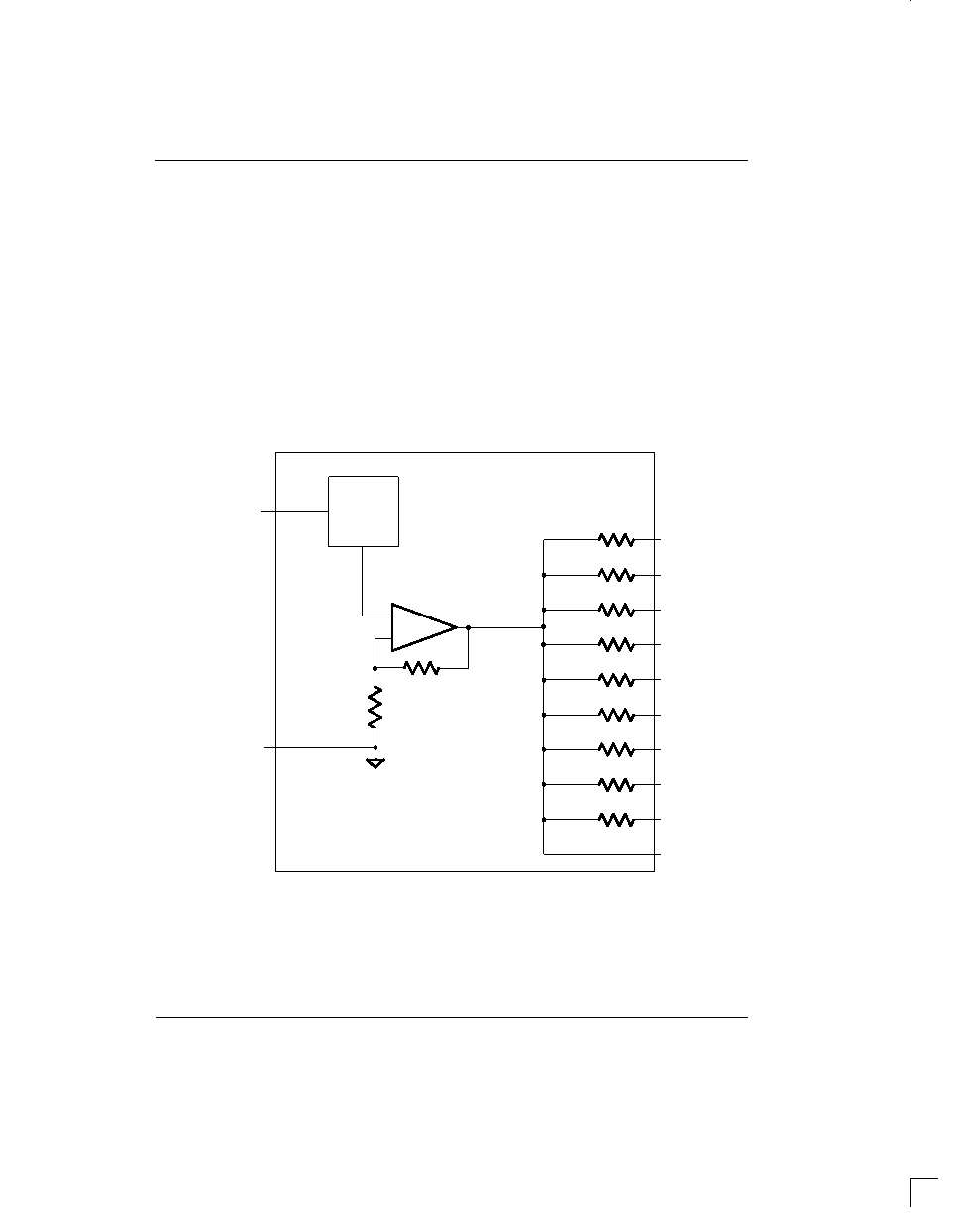 DS2114 070198 2/6 FUNCTIONAL DESCRIPTION The DS2114 consists of a bandgap reference, buffer amplifier, and nine termination resistors (Figure 1). The bandgap reference circuit produces a precise 2.55 volts level which is fed to a buffer amplifier. The buffer pro- duces a 2.85 volts level and is capable of sourcing at least 24 mA into each of the termination resistors when the signal line is low (active). When the driver for a given signal line turns off, the terminator will pull the signal line to 2.85 volts (quiescent state). To handle actively ne- gated SCSI signals, the buffer can sink at least 200 mA and Vref will move less than 60 mV. When all lines settle in the quiescent state, the regulator will consume about 2.5 mA. To ensure proper operation, both the TERMPWR1 and TERMPWR2 pins must be connected to the SCSI bus TERMPWR line and both the VREF1 and VREF2 pins must be tied together externally. Each DS2114 requires a 4.7 µF capacitor connected between the VREF pins and ground. Figure 2 details a typical SCSI bus configu- ration. In an 8–bit wide SCSI bus arrangement (“A” Cable), two DS2114’s would be needed at each end of the SCSI cable in order to terminate the 18 active signal lines. In a 16–bit wide SCSI bus arrangement (“P” Cable), three DS2114’s would be needed at each end of the SCSI cable in order to terminate the 27 active signal lines. DS2114 BLOCK DIAGRAM Figure 1 GND TERMPWR1 TERMPWR2 BANDGAP REFERENCE R1 R2 R3 R4 R5 R6 R7 R8 R9 VREF1 VREF2 + – 110 ohms 110 ohms 110 ohms 110 ohms 110 ohms 110 ohms 110 ohms 110 ohms 110 ohms |
|
|
Link URL |
| Does ALLDATASHEET help your business so far? [ DONATE ] |
About Alldatasheet | Advertisement | Contact us | Privacy Policy | Link to Datasheet | Link Exchange | Manufacturer List All Rights Reserved©Alldatasheet.com |
| Russian : Alldatasheetru.com | Korean : Alldatasheet.co.kr | Spanish : Alldatasheet.es | French : Alldatasheet.fr | Italian : Alldatasheetit.com Portuguese : Alldatasheetpt.com | Polish : Alldatasheet.pl | Vietnamese : Alldatasheet.vn Indian : Alldatasheet.in | Mexican : Alldatasheet.com.mx | British : Alldatasheet.co.uk | New Zealand : Alldatasheet.co.nz |
|
Family Site : ic2ic.com |
icmetro.com |
 Indian ▼
 English
 Chinese
 German
 Japanese
 Russian
 Korean
 Spanish
 French
 Italian
 Portuguese
 Polish
 Vietnamese
 Indian
 Mexican
 British
 New Zealand