 |
Electronic Components Datasheet Search |
|
|
Electronic Components Datasheet Search |
|
MSC8152SVT1000B Datasheet(PDF) 57 Page - Freescale Semiconductor, Inc |
|
|
|||||||||||||||||||||||||||||
MSC8152SVT1000B Datasheet(HTML) 57 Page - Freescale Semiconductor, Inc |
|
|
57 / 68 page 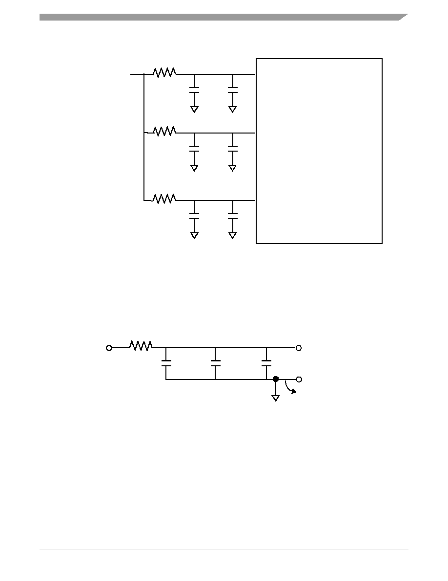 Hardware Design Considerations MSC8152 Dual-Core Digital Signal Processor Data Sheet, Rev. 1 Freescale Semiconductor 57 . Each SerDes PLL power supply must be filtered using a circuit similar to the one shown in Figure 38, to ensure stability of the internal clock. For maximum effectiveness, the filter circuit should be placed as closely as possible to the SRn_PLL_AVDD ball to ensure it filters out as much noise as possible. The ground connection should be near the SRn_PLL_AVDD ball. The 0.003 μF capacitor is closest to the ball, followed by the two 2.2 μF capacitors, and finally the 1 Ω resistor to the board supply plane. The capacitors are connected from SRn_PLL_AVDD to the ground plane. Use ceramic chip capacitors with the highest possible self-resonant frequency. All trances should be kept short, wide, and direct. 3.3 Clock and Timing Signal Board Layout Considerations When laying out the system board, use the following guidelines: • Keep clock and timing signal paths as short as possible and route with 50 Ω impedance. • Use a serial termination resistor placed close to the clock buffer to minimize signal reflection. Use the following equation to compute the resistor value: Rterm = Rim – Rbuf where Rim = trace characteristic impedance Rbuf = clock buffer internal impedance. Figure 37. PLL Supplies Figure 38. SerDes PLL Supplies MSC8156E PLL0_AVDD R C1 C2 PLL1_AVDD R C1 C2 PLL2_AVDD R C1 C2 VDD Power Rail (Voltage Regulator) VSS VSS VSS 1 Ω 2.2 μF 2.2 μF 0.003 μF SRn_PLL_AVDD SRn_PLL_AGND as short as possible GNDSXC VDDSXC |
|
Link URL |
| Does ALLDATASHEET help your business so far? [ DONATE ] |
About Alldatasheet | Advertisement | Contact us | Privacy Policy | Link to Datasheet | Link Exchange | Manufacturer List All Rights Reserved©Alldatasheet.com |
| Russian : Alldatasheetru.com | Korean : Alldatasheet.co.kr | Spanish : Alldatasheet.es | French : Alldatasheet.fr | Italian : Alldatasheetit.com Portuguese : Alldatasheetpt.com | Polish : Alldatasheet.pl | Vietnamese : Alldatasheet.vn Indian : Alldatasheet.in | Mexican : Alldatasheet.com.mx | British : Alldatasheet.co.uk | New Zealand : Alldatasheet.co.nz |
|
Family Site : ic2ic.com |
icmetro.com |
 Indian ▼
 English
 Chinese
 German
 Japanese
 Russian
 Korean
 Spanish
 French
 Italian
 Portuguese
 Polish
 Vietnamese
 Indian
 Mexican
 British
 New Zealand


