 |
Electronic Components Datasheet Search |
|
|
Electronic Components Datasheet Search |
|
ADP196ACBZ-R7 Datasheet(PDF) 9 Page - Analog Devices |
|
|
|||||||||||||||||||||||||||||
ADP196ACBZ-R7 Datasheet(HTML) 9 Page - Analog Devices |
|
|
9 / 12 page 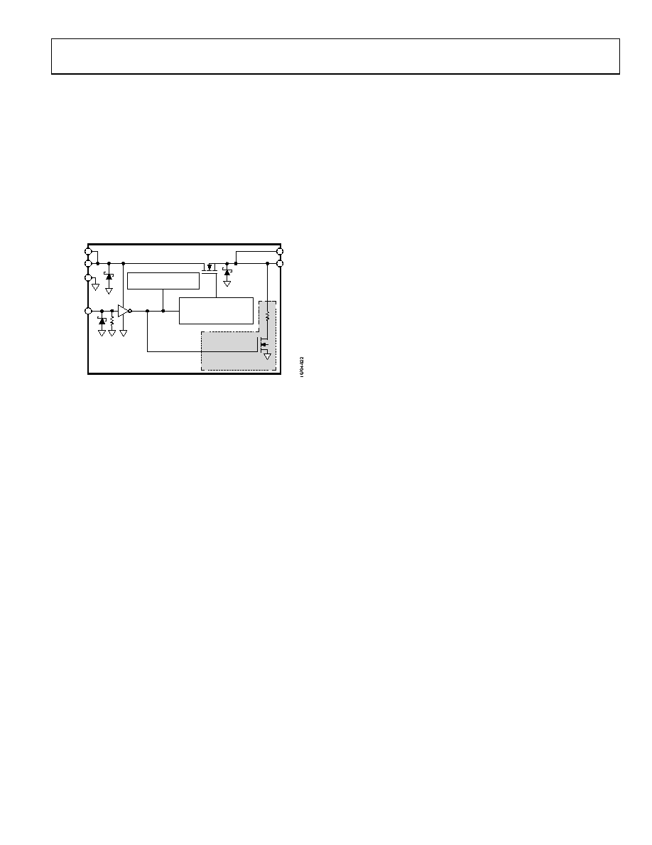 Data Sheet ADP196 Rev. 0 | Page 9 of 12 THEORY OF OPERATION The ADP196 is a high-side NMOS load switch controlled by an internal charge pump. The ADP196 is designed to operate with power supply voltages from 1.8 V to 5.5 V. An internal charge pump biases the NMOS switch to achieve a relatively constant, ultralow on resistance of 10 mΩ across the entire input voltage range (6-ball WLCSP package). The use of the internal charge pump also allows for controlled turn-on times. Turning the NMOS switch on and off is controlled by the enable input, EN, which is capable of interfacing directly to 1.2 V logic signals. GND EN VIN VOUT CHARGE PUMP OVERCURRENT AND SLEW RATE CONTROL OVERTEMPERATURE PROTECTION QOD ADP196-01 ONLY Figure 21. Functional Block Diagram The ADP196 supports 3 A of continuous current as long as TJ is less than 70°C. At 85°C, the rated current decreases to 2.22 A. Overcurrent protection limits the output current to 4 A. The overtemperature protection circuit is activated if the load current causes the junction temperature to exceed 125°C. When this occurs, the overtemperature protection circuitry disables the output until the junction temperature falls below approximately 110°C, at which point the output is reenabled. If the fault condition persists, the output cycles off and on until the fault is removed. Additional protection is provided by an overcurrent limit that forces the device into a constant current mode of operation. The ADP196-01 incorporates a quick output discharge (QOD) circuit to discharge the output capacitance when the ADP196-01 output is disabled. ESD protection structures are shown in the block diagram as Zener diodes (see Figure 21). The ADP196 is a low quiescent current device with a nominal 4 MΩ pull-down resistor on its enable pin (EN). The ADP196 is available in a space-saving 1.0 mm × 1.5 mm, 0.5 mm pitch, 6-ball WLCSP and a tiny 2.0 mm × 2.0 mm × 0.55 mm, 0.65 mm pitch, 6-lead LFCSP. |
|
|
Link URL |
| Does ALLDATASHEET help your business so far? [ DONATE ] |
About Alldatasheet | Advertisement | Contact us | Privacy Policy | Link to Datasheet | Link Exchange | Manufacturer List All Rights Reserved©Alldatasheet.com |
| Russian : Alldatasheetru.com | Korean : Alldatasheet.co.kr | Spanish : Alldatasheet.es | French : Alldatasheet.fr | Italian : Alldatasheetit.com Portuguese : Alldatasheetpt.com | Polish : Alldatasheet.pl | Vietnamese : Alldatasheet.vn Indian : Alldatasheet.in | Mexican : Alldatasheet.com.mx | British : Alldatasheet.co.uk | New Zealand : Alldatasheet.co.nz |
|
Family Site : ic2ic.com |
icmetro.com |
 Indian ▼
 English
 Chinese
 German
 Japanese
 Russian
 Korean
 Spanish
 French
 Italian
 Portuguese
 Polish
 Vietnamese
 Indian
 Mexican
 British
 New Zealand


