|
Electronic Components Datasheet Search |
|
|
Electronic Components Datasheet Search |
|
IR3553 Datasheet(PDF) 18 Page - International Rectifier |
|
|
|||||||||||||||||||||||||||||
IR3553 Datasheet(HTML) 18 Page - International Rectifier |
|
|
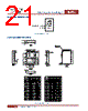
18 / 22 page  July 16, 2014 | DATASHEET V3.3 18 IR3553 40A Integrated PowIRstage® METAL AND COMPONENT PLACEMENT Lead land width should be equal to nominal part lead width. The minimum lead to lead spacing should be ≥ 0.2mm to prevent shorting. Lead land length should be equal to maximum part lead length +0.15 - 0.3 mm outboard extension and 0 to + 0.05mm inboard extension. The outboard extension ensures a large and visible toe fillet, and the inboard extension will accommodate any part misalignment and ensure a fillet. Center pad land length and width should be equal to maximum part pad length and width. Only 0.30mm diameter via shall be placed in the area of the power pad lands and connected to power planes to minimize the noise effect on the IC and to improve thermal performance. 23 16 17 18 19 20 21 22 25 24 5 4 3 2 1 11 10 9 8 15 14 13 12 7 6 Figure 33: Metal and component placement * Contact International Rectifier to receive an electronic PCB Library file in Cadence Allegro or CAD DXF/DWG format. |
|
|
Link URL |
| Does ALLDATASHEET help your business so far? [ DONATE ] |
About Alldatasheet | Advertisement | Contact us | Privacy Policy | Link to Datasheet | Link Exchange | Manufacturer List All Rights Reserved©Alldatasheet.com |
| Russian : Alldatasheetru.com | Korean : Alldatasheet.co.kr | Spanish : Alldatasheet.es | French : Alldatasheet.fr | Italian : Alldatasheetit.com Portuguese : Alldatasheetpt.com | Polish : Alldatasheet.pl | Vietnamese : Alldatasheet.vn Indian : Alldatasheet.in | Mexican : Alldatasheet.com.mx | British : Alldatasheet.co.uk | New Zealand : Alldatasheet.co.nz |
|
Family Site : ic2ic.com |
icmetro.com |
 Indian ▼
 English
 Chinese
 German
 Japanese
 Russian
 Korean
 Spanish
 French
 Italian
 Portuguese
 Polish
 Vietnamese
 Indian
 Mexican
 British
 New Zealand