 |
Electronic Components Datasheet Search |
|
|
Electronic Components Datasheet Search |
|
ADR280ART-R2 Datasheet(PDF) 4 Page - Analog Devices |
|
|
|||||||||||||||||||||||||||||
ADR280ART-R2 Datasheet(HTML) 4 Page - Analog Devices |
|
|
4 / 8 page 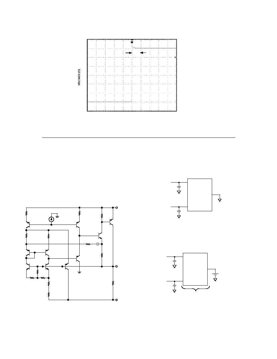 ADR280 –4– ADR280 –5– THEORY OF OPERATION The ADR280 provides the basic core 1.2 V band gap reference. It contains two NPN transistors, Q9 and Q17, with their emitter areas scaled in a fixed ratio.The difference in their Vbes produces a PTAT (proportional to absolute temperature) voltage that cancels the CTAT (complementary to absolute temperature) Q9 Vbe voltage. As a result, a core band gap voltage that is almost a constant 1.2 V over temperature is generated (see Figure 2). Preci- sion laser trimming of the internal resistors and other proprietary circuit techniques are used to enhance the initial accuracy, tem- perature curvature, and temperature drift performance. R1 R3 R5 R7 R9 Q17 Q9 Q18 R8 Q3 R6 Q5 Q6 R4 Q1 PNP3 R2 R12 Q2 Q10 R13 C1 Q7 R10 R11 V– V+ VOUT I1 Figure 2. Simplified Architecture tS 1.2 1.0 0.8 0.6 0.4 0.2 0 2 4 6 8 10 12 14 16 18 20 0 TIME (ms) TPC 7. SettlingTime APPLICATIONS The ADR280 should be decoupled with a 0.1 µF ceramic cap at the output for optimum stability. It is also good practice to include 0.1 µF ceramic caps at the IC supply pin.These capaci- tors should be mounted close to their respective pins (see Figure 3). V+ VOUT 0.1F 0.1F V– ADR280 Figure 3. Basic Configuration The low supply voltage input pin V– can be elevated above ground; a 1.2 V differential voltage can therefore be established above V– (see Figure 4). V+ VOUT 0.1F 0.1F V– ADR280 5V 1.2V 2.5V Figure 4. Floating References REV. A REV. A |
|
|
Link URL |
| Does ALLDATASHEET help your business so far? [ DONATE ] |
About Alldatasheet | Advertisement | Contact us | Privacy Policy | Link to Datasheet | Link Exchange | Manufacturer List All Rights Reserved©Alldatasheet.com |
| Russian : Alldatasheetru.com | Korean : Alldatasheet.co.kr | Spanish : Alldatasheet.es | French : Alldatasheet.fr | Italian : Alldatasheetit.com Portuguese : Alldatasheetpt.com | Polish : Alldatasheet.pl | Vietnamese : Alldatasheet.vn Indian : Alldatasheet.in | Mexican : Alldatasheet.com.mx | British : Alldatasheet.co.uk | New Zealand : Alldatasheet.co.nz |
|
Family Site : ic2ic.com |
icmetro.com |
 Indian ▼
 English
 Chinese
 German
 Japanese
 Russian
 Korean
 Spanish
 French
 Italian
 Portuguese
 Polish
 Vietnamese
 Indian
 Mexican
 British
 New Zealand


