 |
Electronic Components Datasheet Search |
|
|
Electronic Components Datasheet Search |
|
MS6713L Datasheet(PDF) 7 Page - MOSA ELECTRONICS |
|
|
|||||||||||||||||||||||||||||
MS6713L Datasheet(HTML) 7 Page - MOSA ELECTRONICS |
|
|
7 / 14 page 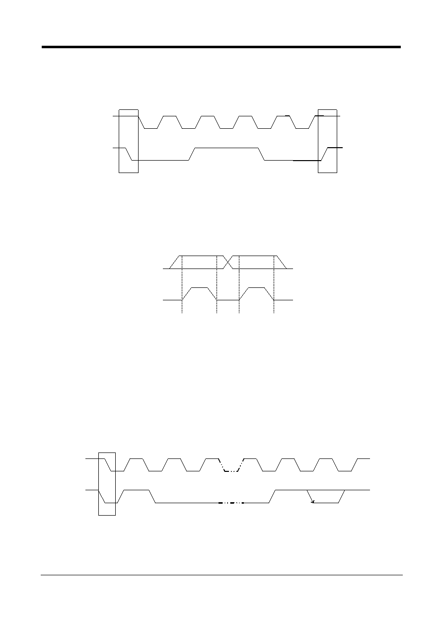 MOSA MS6713L Low Cost 3 Stereo Inputs / 4-Channel Outputs Audio Processor REV 2 7/14 www.mosanalog.com I 2C BUS DESCRIPTION Start and Stop Conditions A start condition is activated when the SCL is set to HIGH and SDA shifts from HIGH to LOW state. The stop condition is activated when SCL is set to HIGH and SDA shifts from LOW to HIGH state. Please refer to the timing diagram below. SDA SCL Start Stop SCL : Serial Clock Line, SDA : Serial Data Line Data Validity A data on the SDA line is considered valid and stable only when the SCL signal is in HIGH state. The HIGH and LOW states of the SDA line can only change when the SCL signal is LOW. Please refer to the figure below. SDA SCL Data line stable, Data valid Data change allowed Byte Format Every byte transmitted to the SDA line consists of 8 bits. Each byte must be followed by an acknowledge bit. The MSB is transmitted first. Acknowledge During the Acknowledge clock pulse, the master (up) put a resistive HIGH level on the SDA line. The peripheral (audio processor) that acknowledges has to pull-down (LOW) the SDA line during the Acknowledge clock pulse so that the SDA line is in a stable LOW state during this clock pulse. Please refer to the diagram below. SCL SDA MSB Acknowledge 1 2 3 7 8 9 Start The audio processor that has been addressed has to generate an Acknowledge after receiving each byte, otherwise, the SDA line will remain at the HIGH level during the ninth (9 th) clock pulse. In this case, the master transmitter can generate the STOP information in order to abort the transfer. |
|
|
Link URL |
| Does ALLDATASHEET help your business so far? [ DONATE ] |
About Alldatasheet | Advertisement | Contact us | Privacy Policy | Link to Datasheet | Link Exchange | Manufacturer List All Rights Reserved©Alldatasheet.com |
| Russian : Alldatasheetru.com | Korean : Alldatasheet.co.kr | Spanish : Alldatasheet.es | French : Alldatasheet.fr | Italian : Alldatasheetit.com Portuguese : Alldatasheetpt.com | Polish : Alldatasheet.pl | Vietnamese : Alldatasheet.vn Indian : Alldatasheet.in | Mexican : Alldatasheet.com.mx | British : Alldatasheet.co.uk | New Zealand : Alldatasheet.co.nz |
|
Family Site : ic2ic.com |
icmetro.com |
 Indian ▼
 English
 Chinese
 German
 Japanese
 Russian
 Korean
 Spanish
 French
 Italian
 Portuguese
 Polish
 Vietnamese
 Indian
 Mexican
 British
 New Zealand


