 |
Electronic Components Datasheet Search |
|
|
Electronic Components Datasheet Search |
|
The question interval is too short.
Please try again in a few seconds.

Hello, Please ask a question about SP6685 Datasheet
# Example questions:
➢ What is a key consideration when using multiple leds in parallel with the sp6685 to ensure optimal performance?
➢ In figure 31, what is the purpose of the 'ifb' resistor, and how does its value relate to the flash current setting?
➢ What are the typical input voltage (vin) and output current ranges for the sp6685?
| Part No. | SP6685 |
| Manufacturer | SIPEX |
| Size | 278 Kbytes |
| Pages | 16 pages |
| Description | 700mA Buck/Boost Charge Pump LED Driver |






1. SP6685 Overview:
️· Function: The SP6685 is a 700mA Buck-Boost charge pump LED driver. It's designed to drive LEDs efficiently and provides features for various operating modes (like Flash and Torch).
️· Key Features: It supports multiple LEDs in parallel, offers good current regulation, and is optimized for applications where efficiency and brightness are important.
2. Typical Performance Characteristics (From Graphs and Descriptions):
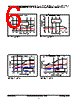
️· Startup: Graphs show the startup behavior for both 150mA Torch mode and 700mA Flash mode. These illustrate how quickly the output voltage and current reach their stable operating points.
️· Efficiency: Efficiency graphs demonstrate how the efficiency of the driver varies with input voltage (Vin).
️· Output Current vs. Input Voltage: Graphs showing how the output current changes as the input voltage varies.
️· Mode Switching: The diagrams showcase the switching behavior between Torch (lower current) and Flash (higher current) modes.
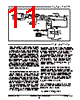
3. Application Circuit (Figure 31):
️· Multiple LED Support: A dedicated circuit (Figure 31) shows how to connect multiple LEDs in parallel to the SP6685. The design emphasizes the importance of matching forward voltages of the LEDs for optimal current sharing.
️· Component Values:
- Vin: Input Voltage Range: 3.0V - 4.2V
- Cin: Input Capacitor: 10uF
- C1 & C2: Capacitors for Filtering/Stability (Values shown in diagrams)
- R_SET: 139kΩ (Sets output current)
- R_EN: 10kΩ (Enable resistor)
- R_FB: 0.33Ω (Feedback resistor)
- Cout: 4.7uF
- CF: 1uF
4. Key Components and Settings (Figure 31, GM5BW0):
️· Jumper settings: The component layout and diagrams emphasize specific jumper settings (often labeled as GM5BW0) that likely control the flash/torch configuration, or other operational parameters.
️· IFB (Feedback): Seems to regulate current.
️· ISET (Set): Sets the LED current level.
️· VFB (Feedback Voltage): Set by the resistors, often 50mV for Torch and 100mV for Flash. This sets the current.
️· Switch (SW2): Used to enable the Flash mode.
5. Important Considerations:
️· LED Matching: Matching the forward voltage (Vf) and forward current (If) of the LEDs is crucial for balancing the current and preventing overheating.
️· Component Selection: The correct selection of capacitors and resistors is essential for stability and performance.
️· Modes: Torch (low current) and Flash (high current) modes allow for adjusting brightness and power consumption.
In essence, this documentation provides a comprehensive guide to designing and implementing LED lighting systems using the SP6685 driver IC. It covers the IC's key features, performance characteristics, application circuits, and important design considerations.
1. SP6685 Overview:
️· Function: The SP6685 is a 700mA Buck-Boost charge pump LED driver. It's designed to drive LEDs efficiently and provides features for various operating modes (like Flash and Torch).
️· Key Features: It supports multiple LEDs in parallel, offers good current regulation, and is optimized for applications where efficiency and brightness are important.
2. Typical Performance Characteristics (From Graphs and Descriptions):
️· Startup: Graphs show the startup behavior for both 150mA Torch mode and 700mA Flash mode. These illustrate how quickly the output voltage and current reach their stable operating points.
️· Efficiency: Efficiency graphs demonstrate how the efficiency of the driver varies with input voltage (Vin).
️· Output Current vs. Input Voltage: Graphs showing how the output current changes as the input voltage varies.
️· Mode Switching: The diagrams showcase the switching behavior between Torch (lower current) and Flash (higher current) modes.
3. Application Circuit (Figure 31):
️· Multiple LED Support: A dedicated circuit (Figure 31) shows how to connect multiple LEDs in parallel to the SP6685. The design emphasizes the importance of matching forward voltages of the LEDs for optimal current sharing.
️· Component Values:
- Vin: Input Voltage Range: 3.0V - 4.2V
- Cin: Input Capacitor: 10uF
- C1 & C2: Capacitors for Filtering/Stability (Values shown in diagrams)
- R_SET: 139kΩ (Sets output current)
- R_EN: 10kΩ (Enable resistor)
- R_FB: 0.33Ω (Feedback resistor)
- Cout: 4.7uF
- CF: 1uF
4. Key Components and Settings (Figure 31, GM5BW0):
️· Jumper settings: The component layout and diagrams emphasize specific jumper settings (often labeled as GM5BW0) that likely control the flash/torch configuration, or other operational parameters.
️· IFB (Feedback): Seems to regulate current.
️· ISET (Set): Sets the LED current level.
️· VFB (Feedback Voltage): Set by the resistors, often 50mV for Torch and 100mV for Flash. This sets the current.
️· Switch (SW2): Used to enable the Flash mode.
5. Important Considerations:
️· LED Matching: Matching the forward voltage (Vf) and forward current (If) of the LEDs is crucial for balancing the current and preventing overheating.
️· Component Selection: The correct selection of capacitors and resistors is essential for stability and performance.
️· Modes: Torch (low current) and Flash (high current) modes allow for adjusting brightness and power consumption.
In essence, this documentation provides a comprehensive guide to designing and implementing LED lighting systems using the SP6685 driver IC. It covers the IC's key features, performance characteristics, application circuits, and important design considerations.
| Part No. | SP6685 |
| Manufacturer | SIPEX |
| Size | 278 Kbytes |
| Pages | 16 pages |
| Description | 700mA Buck/Boost Charge Pump LED Driver |
| Does ALLDATASHEET help your business so far? [ DONATE ] |
About Alldatasheet | Advertisement | Contact us | Privacy Policy | Link to Datasheet | Link Exchange | Manufacturer List All Rights Reserved©Alldatasheet.com |
| Russian : Alldatasheetru.com | Korean : Alldatasheet.co.kr | Spanish : Alldatasheet.es | French : Alldatasheet.fr | Italian : Alldatasheetit.com Portuguese : Alldatasheetpt.com | Polish : Alldatasheet.pl | Vietnamese : Alldatasheet.vn Indian : Alldatasheet.in | Mexican : Alldatasheet.com.mx | British : Alldatasheet.co.uk | New Zealand : Alldatasheet.co.nz |
|
Family Site : ic2ic.com |
icmetro.com |
 Indian ▼
  English
 Chinese
 German
 Japanese
 Russian
 Korean
 Spanish
 French
 Italian
 Portuguese
 Polish
 Vietnamese
 Mexican
 British
 New Zealand