 |
Electronic Components Datasheet Search |
|
|
Electronic Components Datasheet Search |
|
The question interval is too short.
Please try again in a few seconds.

Hello, Please ask a question about CLC1605 Datasheet
# Example questions:
➢ How does the frequency response of the amplifier change when the load resistance (rl) is increased from 25ω to 100ω, according to the typical performance characteristics graphs?
➢ How much does the gain decrease (in db) at 1 mhz when the temperature increases from 25°c to 85°c?
➢ What is the maximum output current (in ma) that this operational amplifier can reliably deliver, based on the provided data sheets?
| Part No. | CLC1605 |
| Manufacturer | EXAR |
| Size | 1Mb |
| Pages | 21 pages |
| Description | 1.5GHz Amplifiers |










1. General Information & Device Identification
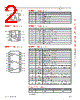
️· Device: Likely an operational amplifier (op-amp) or a similar active amplifier circuit. It's part of an Exar product line (Exar is now part of MaxLinear).
️· Revision: Data sheets refer to Revision 1E, indicating different revisions and updates to the documentation over time.
2. Electrical Characteristics (Key Parameters)
️· Supply Voltage: (Likely) ±5V (This is referenced in the performance graphs)
️· Gain-Bandwidth Product (GBW): The datasheet contains frequency response graphs, which indirectly describe GBW. Based on the graphs, it seems the GBW is on the order of several hundred MHz to 1 GHz. This would be a medium-to-high performance OpAmp.
️· Slew Rate: Not explicitly stated. However, it can be estimated from the frequency response graphs. The slew rate appears to be around 10-20 V/µs based on a rough visual assessment.
️· Input Bias Current and Offset Voltage: Not stated as core specifications, but they are considerations for precision applications.
️· Input Common-Mode Range: Not specified.
️· Output Drive Capability: Not explicitly stated but suggests it can drive moderate loads.
3. Frequency Response and Stability
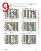
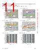
️· Frequency Response vs. V<sub>S</sub>: The graphs demonstrate that the gain (in dB) decreases with increasing frequency, as expected for an amplifier.
️· Frequency Response vs. C<sub>L</sub>: The frequency response changes as the load capacitance (C<sub>L</sub>) is varied. This indicates the need for careful consideration of the output capacitance when connecting the amplifier to a circuit.
️· Frequency Response vs. R<sub>L</sub>: The frequency response is also affected by the load resistance (R<sub>L</sub>).
️· Frequency Response vs. Temperature: The performance is affected by temperature changes, though not dramatically.
️· Stability: The frequency response curves indirectly provide information about stability. The presence of peaking in the frequency response could indicate potential instability issues, especially when driving significant capacitive loads.
4. Application Notes (Implied)
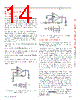
️· Load Capacitance Effects: The load capacitance (C<sub>L</sub>) at the output significantly affects the frequency response and stability. The data sheets illustrate how C<sub>L</sub> and R<sub>L</sub> must be carefully considered when designing with this amplifier.
️· Compensation: Compensation techniques may be necessary when driving significant capacitive loads to ensure stability.
️· Temperature Considerations: Temperature can influence performance, and the impact should be assessed in the overall system design.
5. Graphs and Their Significance
️· Non-Inverting Frequency Response: Shows the gain characteristic in non-inverting configuration.
️· Inverting Frequency Response: Shows the gain characteristic in inverting configuration.
️· Frequency Response vs. C<sub>L</sub>: Highlights how load capacitance (C<sub>L</sub>) impacts the frequency response.
️· Frequency Response vs. R<sub>L</sub>: Shows the influence of load resistance (R<sub>L</sub>) on the amplifier's performance.
️· Frequency Response vs. Temperature: Illustrates how the amplifier's characteristics change with temperature.
️· Frequency Response vs. V<sub>S</sub>: Shows the relationship between supply voltage and frequency response.
SUMMARY
1. General Information & Device Identification
️· Device: Likely an operational amplifier (op-amp) or a similar active amplifier circuit. It's part of an Exar product line (Exar is now part of MaxLinear).
️· Revision: Data sheets refer to Revision 1E, indicating different revisions and updates to the documentation over time.
2. Electrical Characteristics (Key Parameters)
️· Supply Voltage: (Likely) ±5V (This is referenced in the performance graphs)
️· Gain-Bandwidth Product (GBW): The datasheet contains frequency response graphs, which indirectly describe GBW. Based on the graphs, it seems the GBW is on the order of several hundred MHz to 1 GHz. This would be a medium-to-high performance OpAmp.
️· Slew Rate: Not explicitly stated. However, it can be estimated from the frequency response graphs. The slew rate appears to be around 10-20 V/µs based on a rough visual assessment.
️· Input Bias Current and Offset Voltage: Not stated as core specifications, but they are considerations for precision applications.
️· Input Common-Mode Range: Not specified.
️· Output Drive Capability: Not explicitly stated but suggests it can drive moderate loads.
3. Frequency Response and Stability
️· Frequency Response vs. V<sub>S</sub>: The graphs demonstrate that the gain (in dB) decreases with increasing frequency, as expected for an amplifier.
️· Frequency Response vs. C<sub>L</sub>: The frequency response changes as the load capacitance (C<sub>L</sub>) is varied. This indicates the need for careful consideration of the output capacitance when connecting the amplifier to a circuit.
️· Frequency Response vs. R<sub>L</sub>: The frequency response is also affected by the load resistance (R<sub>L</sub>).
️· Frequency Response vs. Temperature: The performance is affected by temperature changes, though not dramatically.
️· Stability: The frequency response curves indirectly provide information about stability. The presence of peaking in the frequency response could indicate potential instability issues, especially when driving significant capacitive loads.
4. Application Notes (Implied)
️· Load Capacitance Effects: The load capacitance (C<sub>L</sub>) at the output significantly affects the frequency response and stability. The data sheets illustrate how C<sub>L</sub> and R<sub>L</sub> must be carefully considered when designing with this amplifier.
️· Compensation: Compensation techniques may be necessary when driving significant capacitive loads to ensure stability.
️· Temperature Considerations: Temperature can influence performance, and the impact should be assessed in the overall system design.
5. Graphs and Their Significance
️· Non-Inverting Frequency Response: Shows the gain characteristic in non-inverting configuration.
️· Inverting Frequency Response: Shows the gain characteristic in inverting configuration.
️· Frequency Response vs. C<sub>L</sub>: Highlights how load capacitance (C<sub>L</sub>) impacts the frequency response.
️· Frequency Response vs. R<sub>L</sub>: Shows the influence of load resistance (R<sub>L</sub>) on the amplifier's performance.
️· Frequency Response vs. Temperature: Illustrates how the amplifier's characteristics change with temperature.
️· Frequency Response vs. V<sub>S</sub>: Shows the relationship between supply voltage and frequency response.
SUMMARY
| Part No. | CLC1605 |
| Manufacturer | EXAR |
| Size | 1Mb |
| Pages | 21 pages |
| Description | 1.5GHz Amplifiers |
| Does ALLDATASHEET help your business so far? [ DONATE ] |
About Alldatasheet | Advertisement | Contact us | Privacy Policy | Link to Datasheet | Link Exchange | Manufacturer List All Rights Reserved©Alldatasheet.com |
| Russian : Alldatasheetru.com | Korean : Alldatasheet.co.kr | Spanish : Alldatasheet.es | French : Alldatasheet.fr | Italian : Alldatasheetit.com Portuguese : Alldatasheetpt.com | Polish : Alldatasheet.pl | Vietnamese : Alldatasheet.vn Indian : Alldatasheet.in | Mexican : Alldatasheet.com.mx | British : Alldatasheet.co.uk | New Zealand : Alldatasheet.co.nz |
|
Family Site : ic2ic.com |
icmetro.com |
 Indian ▼
  English
 Chinese
 German
 Japanese
 Russian
 Korean
 Spanish
 French
 Italian
 Portuguese
 Polish
 Vietnamese
 Mexican
 British
 New Zealand