 |
Electronic Components Datasheet Search |
|
|
Electronic Components Datasheet Search |
|
USB2GPIOISO Datasheet(PDF) 3 Page - Maxim Integrated Products |
|
|
|||||||||||||||||||||||||||||
USB2GPIOISO Datasheet(HTML) 3 Page - Maxim Integrated Products |
|
|
3 / 8 page 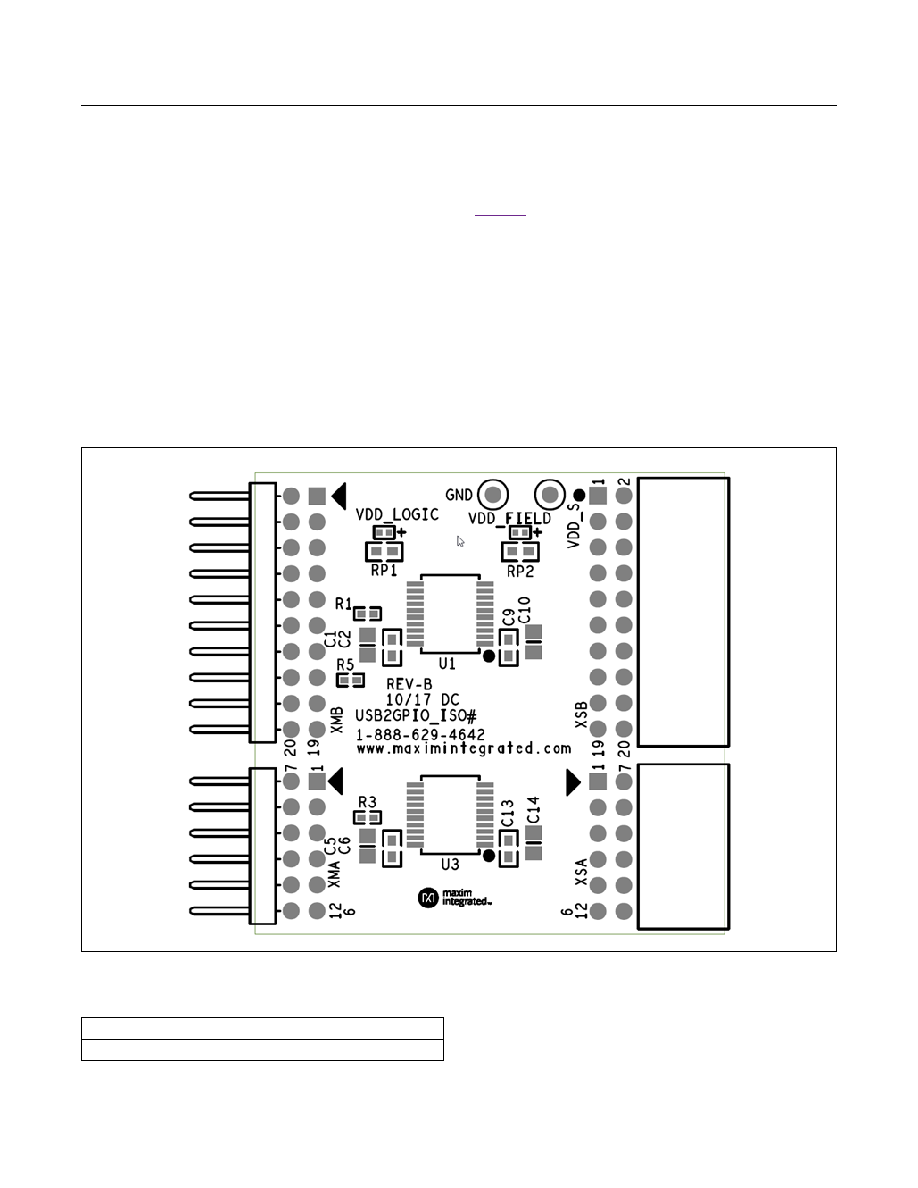 Maxim Integrated │ 3 www.maximintegrated.com Evaluates: USB2GPIOISO USB2GPIOISO# Adapter Board Master and Slave Connectors The USB2GPIOISO# is designed to receive power (VDD_M, GNDM and VDD_S, GNDS) from external boards through the connectors XMA, XMB, XSA and XSB. VDD_S is defined by the type of board connected to the slave connectors. When the user selects certain tab in the Munich GUI, VDD_M is automatically set to certain level, either 1.8V, 2.5V, 3.3V, or 5.0V. Note that USB2GPIOISO# does NOT provide power using VDD_S to the Pmod or EV kit board, but instead expects to receive power from those boards. Test points VDD_S and GND are provided to allow powering the USB2GPIOISO# slave side and Pmod or EV kit boards with external power supply. Figure 4 shows the top view of the USB2GPIOISO# board, with the different connectors and the pin 1 identifiers. Note there are no jumpers or shunts on this board, all configuration is done under software control. Care should be taken to only insert the boards in the correct way as the connectors are not keyed to avoid false insertions. Reversing the connections (by turning the Pmod board upside down for example) may result in damage to the USB2GPIOISO# Pmod or EV kit board. Two LEDs are included to indicate if VDD_M and VDD_S are powered. #Denotes RoHS compliant Figure 4. USB2GPIOISO# Orientation and Pinouts Ordering Information PART TYPE USB2GPIOISO# Adapter Board |
|
|
Link URL |
| Does ALLDATASHEET help your business so far? [ DONATE ] |
About Alldatasheet | Advertisement | Contact us | Privacy Policy | Link to Datasheet | Link Exchange | Manufacturer List All Rights Reserved©Alldatasheet.com |
| Russian : Alldatasheetru.com | Korean : Alldatasheet.co.kr | Spanish : Alldatasheet.es | French : Alldatasheet.fr | Italian : Alldatasheetit.com Portuguese : Alldatasheetpt.com | Polish : Alldatasheet.pl | Vietnamese : Alldatasheet.vn Indian : Alldatasheet.in | Mexican : Alldatasheet.com.mx | British : Alldatasheet.co.uk | New Zealand : Alldatasheet.co.nz |
|
Family Site : ic2ic.com |
icmetro.com |
 Indian ▼
 English
 Chinese
 German
 Japanese
 Russian
 Korean
 Spanish
 French
 Italian
 Portuguese
 Polish
 Vietnamese
 Indian
 Mexican
 British
 New Zealand


