 |
Electronic Components Datasheet Search |
|
|
Electronic Components Datasheet Search |
|
EM357-RTR Datasheet(PDF) 141 Page - Silicon Laboratories |
|
|
|||||||||||||||||||||||||||||
EM357-RTR Datasheet(HTML) 141 Page - Silicon Laboratories |
|
|
141 / 241 page 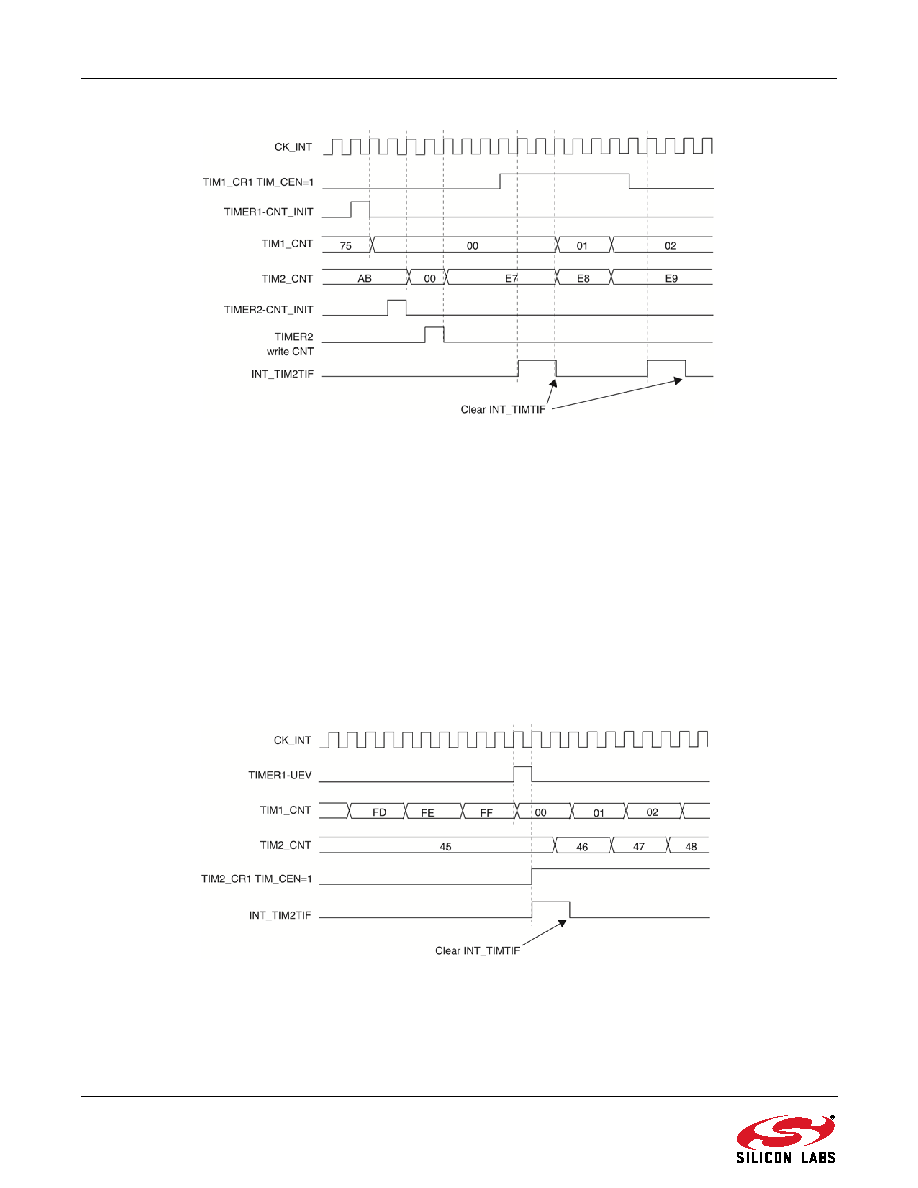 141 Rev 1.3 Figure 9.33. Gating Timer 2 with Enable of Timer 1 9.3.14.3. Using One Timer to Start the Other Timer In this example (see Figure 9.34), the enable of Timer 2 is set with the UEV of Timer 1. Timer 2 starts counting from its current value (which can be non-zero) on the divided internal clock as soon as Timer 1 generates the UEV. When Timer 2 receives the trigger signal its TIM_CEN bit is automatically set and the counter counts until 0 is written to the TIM_CEN bit in the TIM2_CR1 register. Both counter clock frequencies are divided by 3 by the prescaler compared to CK_INT (fCK_CNT = fCK_INT/3). Configure Timer 1 in master mode to send its UEV as trigger output: WriteTIM_MMS = 010 in the TIM1_CR2 register. Configure the Timer 1 period (TIM1_ARR register). Configure Timer 2 to get the input trigger from Timer 1: Write TIM_TS = 000 in the TIM2_SMCR register. Configure Timer 2 in trigger mode. Write TIM_SMS = 110 in the TIM2_SMCR register. Start Timer 1: Write 1 in the TIM_CEN bit in theTIM1_CR1 register. Figure 9.34. Triggering Timer 2 with Update of Timer 1 As in the previous example, both counters can be initialized before starting counting. Figure 9.35 shows the behavior with the same configuration shown in Figure 9.34, but in trigger mode instead of gated mode (TIM_SMS = 110 in the TIM2_SMCR register). |
|
Link URL |
| Does ALLDATASHEET help your business so far? [ DONATE ] |
About Alldatasheet | Advertisement | Contact us | Privacy Policy | Link to Datasheet | Link Exchange | Manufacturer List All Rights Reserved©Alldatasheet.com |
| Russian : Alldatasheetru.com | Korean : Alldatasheet.co.kr | Spanish : Alldatasheet.es | French : Alldatasheet.fr | Italian : Alldatasheetit.com Portuguese : Alldatasheetpt.com | Polish : Alldatasheet.pl | Vietnamese : Alldatasheet.vn Indian : Alldatasheet.in | Mexican : Alldatasheet.com.mx | British : Alldatasheet.co.uk | New Zealand : Alldatasheet.co.nz |
|
Family Site : ic2ic.com |
icmetro.com |
 Indian ▼
 English
 Chinese
 German
 Japanese
 Russian
 Korean
 Spanish
 French
 Italian
 Portuguese
 Polish
 Vietnamese
 Indian
 Mexican
 British
 New Zealand


