 |
Electronic Components Datasheet Search |
|
|
Electronic Components Datasheet Search |
|
ATS665LSG Datasheet(PDF) 8 Page - Allegro MicroSystems |
|
|
|||||||||||||||||||||||||||||
ATS665LSG Datasheet(HTML) 8 Page - Allegro MicroSystems |
|
|
8 / 18 page 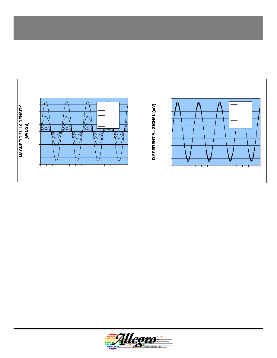 ATS665LSG TRUE ZERO-SPEED GEAR TOOTH SENSOR SENSOR OPERATION: AUTOMATIC GAIN CONTROL (AGC) The patented self-calibrating circuitry is unique. After each power up, the device measures the peak-to-peak magnetic signal. The gain of the sensor is then adjusted which keeps the internal signal amplitude constant over the air gap range of the device. This feature provides operational characteristics independent of air gap. DIFFERENTIAL MAGNETIC SIGNAL WITH INCREASING AIR GAP -1000 -800 -600 -400 -200 0 200 400 600 800 1000 0123 456789 10 11 12 13 14 15 TARGET POSITION [DEGREES] 0.25 mm 0.50 mm 1.00 mm 1.50 mm 2.00 mm Magnetic Signal with no Amplification DIFFERENTIAL ELECTRICAL SIGNAL WITH INCREASING AIR GAP -1000 -800 -600 -400 -200 0 200 400 600 800 1000 0 123 4 56789 10 11 12 13 14 15 TARGET POSITION [DEGREES] 0.25 mm 0.50 mm 1.00 mm 1.50 mm 2.00 mm Electrical Signal after AGC SENSOR OPERATION: OFFSET ADJUST In addition to normalizing performance over air gap, the gain control circuitry also reduces the effect of chip, magnet, and installation offsets. This is accomplished using two D/A converters that capture the peak and valley of the signal and use it as a reference for the switching comparator. If induced offsets bias the absolute signal up or down, AGC and the dynamic DAC behavior work to normalize and reduce the impact of the offset on sensor performance. Final Version, Rev 1.0; DSD; 01Aug03 Page 8 Worcester, Massachusetts 01615-0036 (508) 853-5000 Copyright © 1993, 1995 Allegro MicroSystems, Inc. 115 Northeast Cutoff, Box 15036 |
|
|
Link URL |
| Does ALLDATASHEET help your business so far? [ DONATE ] |
About Alldatasheet | Advertisement | Contact us | Privacy Policy | Link to Datasheet | Link Exchange | Manufacturer List All Rights Reserved©Alldatasheet.com |
| Russian : Alldatasheetru.com | Korean : Alldatasheet.co.kr | Spanish : Alldatasheet.es | French : Alldatasheet.fr | Italian : Alldatasheetit.com Portuguese : Alldatasheetpt.com | Polish : Alldatasheet.pl | Vietnamese : Alldatasheet.vn Indian : Alldatasheet.in | Mexican : Alldatasheet.com.mx | British : Alldatasheet.co.uk | New Zealand : Alldatasheet.co.nz |
|
Family Site : ic2ic.com |
icmetro.com |
 Indian ▼
 English
 Chinese
 German
 Japanese
 Russian
 Korean
 Spanish
 French
 Italian
 Portuguese
 Polish
 Vietnamese
 Indian
 Mexican
 British
 New Zealand


