|
Electronic Components Datasheet Search |
|
|
Electronic Components Datasheet Search |
|
25CS160 Datasheet(PDF) 9 Page - Microchip Technology |
|
|
|||||||||||||||||||||||||||||
25CS160 Datasheet(HTML) 9 Page - Microchip Technology |
|
|
9 / 53 page 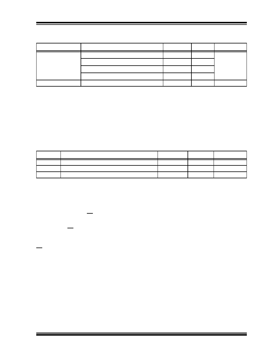 2026 Microchip Technology Inc. and its subsidiaries Preliminary DS20007008B-page 9 25CS160 1.1 Power-Up Requirements and Default Conditions During a power-up sequence, the VCC supplied to the 25CS160 should monotonically rise from VSS to the minimum VCC level, as specified in Table 1-1, with a slew rate no faster than 0.1 V/µs. 1.1.1 DEVICE POWER-ON RESET To prevent spurious events from happening during a power-up sequence, the 25CS160 includes a Power-On Reset (POR) circuit. Upon power-up, the device will not respond to any instructions until the VCC level crosses the internal voltage threshold (VPOR) that brings the device out of Reset and into Standby mode. Microchip recommends that CS follows the rise of VCC at power-up through the use of a pull-up resistor. The system designer must ensure that no instruction is sent to the device and CS is driven high until the VCC supply reaches a stable value greater than the minimum VCC level. Once VCC has surpassed the minimum level, the SPI host must wait at least TVCSL before asserting the CS pin. See Table 1-4 for the values associated with these power-up parameters. If an event occurs in the system where the VCC level supplied to the 25CS160 drops below the maximum VPOR level specified, it is recommended that a full power cycle sequence be performed by first driving the VCC pin to VSS, waiting at least the minimum TPOFF time and then performing a new power-up sequence in compliance with the requirements defined in this section. TABLE 1-3: EEPROM CELL PERFORMANCE CHARACTERISTICS Operation Test Condition Min. Max. Units Write Endurance(1) TA = +25°C 4,000,000 — Write Cycles TA = +85°C 1,200,000 — TA = +125°C 600,000 — TA = +150°C 400,000 — Data Retention(1) TA = +55°C 200 — Years Note 1: Performance is determined through characterization and the qualification process. TABLE 1-4: POWER-UP CONDITIONS Symbol Parameter Min. Max. Units TVCSL Minimum VCC to Chip Select Low Time 100 — µs VPOR Power-On Reset Threshold Voltage — 1.5 V TPOFF Minimum time at VCC = 0V between power cycles 1 — ms |
|
Link URL |
| Does ALLDATASHEET help your business so far? [ DONATE ] |
About Alldatasheet | Advertisement | Contact us | Privacy Policy | Link to Datasheet | Link Exchange | Manufacturer List All Rights Reserved©Alldatasheet.com |
| Russian : Alldatasheetru.com | Korean : Alldatasheet.co.kr | Spanish : Alldatasheet.es | French : Alldatasheet.fr | Italian : Alldatasheetit.com Portuguese : Alldatasheetpt.com | Polish : Alldatasheet.pl | Vietnamese : Alldatasheet.vn Indian : Alldatasheet.in | Mexican : Alldatasheet.com.mx | British : Alldatasheet.co.uk | New Zealand : Alldatasheet.co.nz |
|
Family Site : ic2ic.com |
icmetro.com |
 Indian ▼
 English
 Chinese
 German
 Japanese
 Russian
 Korean
 Spanish
 French
 Italian
 Portuguese
 Polish
 Vietnamese
 Indian
 Mexican
 British
 New Zealand