|
Electronic Components Datasheet Search |
|
|
Electronic Components Datasheet Search |
|
MUL1-R3 Datasheet(PDF) 15 Page - ABB |
|
|
|||||||||||||||||||||||||||||
MUL1-R3 Datasheet(HTML) 15 Page - ABB |
|
|
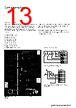
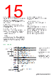
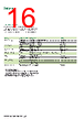
15 / 28 page 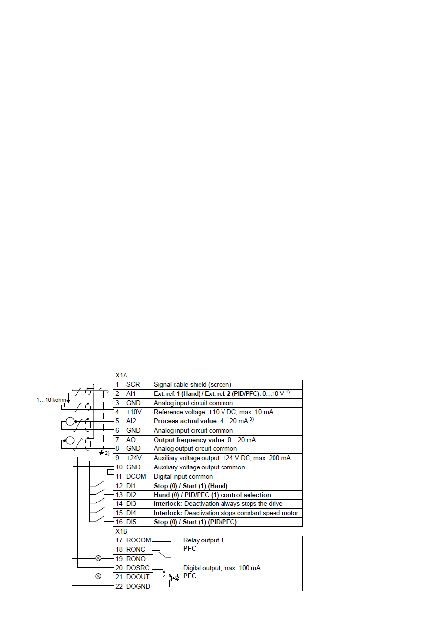 Catalog | ABB general purpose drives ACS310 15 Auxiliary motors start and stop delay Delay stabilizes the contactors before starting or stopping a motor. Parameter 8115 AUX MOT START D is left to its default value 5 s. Parameter 8116 AUX MOT STOP D is left to it’s default value 20 s. Number of auxiliary motors and motors in total Parameter 8117 NR OF AUX MOT is set to 2. Parameter 8127 MOTORS is set to 3. Autochange functionality for SPFC The Autochange functionality for SPFC equalizes duty time between multiple motors, when auxiliary motors are not running. The time interval between motor changes is managed with parameter 8118. Interlocks Interlock detects if any of the pumps are unavailable and starts the next available pump, when used. Set parameter 8120 INTERLOCKS to take input from DI3 in this example (depends of the number of interlocks and how thay are connected). Default I/O settings 1. Hand: 0…10 V -> 0…50 Hz. PID/PFC: 0…10 V -> 0…100% PID setpoint. 2. 360 degree grounding under a clamp. 3. The signal source must be powered externally. See the manufacturer’s instructions. Start delay for speed controlled motor Parameter 8122 PFC START DELAY is left to its default value 0,5 s. Enabling pump and fan control Parameter 8123 PFC ENABLE is set to 3 (SPFC + AUTOCHANGE) Relay configuration Relay configuration depends how many and how the motors are connected. Note! The macro SPFC already sets Transistor output parameter 1805 DO SIGNAL to PFC as an additional relay output which is connected. Parameter 1401 RELAY OUTPUT 1 is set to PFC Parameter 1402 RELAY OUTPUT 2 is set to PFC |
|
Link URL |
| Does ALLDATASHEET help your business so far? [ DONATE ] |
About Alldatasheet | Advertisement | Contact us | Privacy Policy | Link to Datasheet | Link Exchange | Manufacturer List All Rights Reserved©Alldatasheet.com |
| Russian : Alldatasheetru.com | Korean : Alldatasheet.co.kr | Spanish : Alldatasheet.es | French : Alldatasheet.fr | Italian : Alldatasheetit.com Portuguese : Alldatasheetpt.com | Polish : Alldatasheet.pl | Vietnamese : Alldatasheet.vn Indian : Alldatasheet.in | Mexican : Alldatasheet.com.mx | British : Alldatasheet.co.uk | New Zealand : Alldatasheet.co.nz |
|
Family Site : ic2ic.com |
icmetro.com |
 Indian ▼
 English
 Chinese
 German
 Japanese
 Russian
 Korean
 Spanish
 French
 Italian
 Portuguese
 Polish
 Vietnamese
 Indian
 Mexican
 British
 New Zealand