|
Electronic Components Datasheet Search |
|
|
Electronic Components Datasheet Search |
|
962-7DA1-135 Datasheet(PDF) 13 Page - Magnetrol International, Inc. |
|
|
|||||||||||||||||||||||||||||
962-7DA1-135 Datasheet(HTML) 13 Page - Magnetrol International, Inc. |
|
|
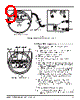
13 / 36 page  13 51-646 Echotel® Model 961 & 962 Ultrasonic Level Switches TIME DELAY LEVEL TEST MALF TEST MALF RELAY FAULT WET LEVEL MALF MODEL 961 NC C NO NC C NO NC C NO L2 L1 High/Low DIP Switch Independent/Joint DIP Switch Level Test Pushbutton Malfunction Test Pushbutton Hi I Lo J Time Delay Pot to decrease delay to increase delay Turn Turn Figure 14 Model 961 Line Power Configuration 2.5.1.1 Time Delay Potentiometer The time delay potentiometer is typically used in applica- tions where turbulence or splashing may cause false level alarms. This is a 25-turn pot with a factory default setting of 0.5 seconds. If desired, this pot may be turned clockwise to increase the response time from the standard 0.5 seconds to a maximum of 45 seconds. Turning the pot counter- clockwise decreases the time delay. The WET LED is not influenced by the time delay pot. As an example, turning the pot clockwise several turns will put a time delay into the 961. Immersing the tip of the transducer in water with the Hi/Lo switch in the Hi posi- tion, will produce the following results: • WET LED will immediately turn on • After the time delay the LEVEL LED will turn off and the DPDT process level relay will de-energize When removing the tip of the transducer from the water the WET LED will immediately turn off. After the time delay the LEVEL LED will turn on and DPDT process level relay will energize. 2.5.1.2 Level Test Push Button The level test push button is used to manually test the DPDT process level relay. Pressing this push button reverses the state of the DPDT relay, from energized to de-ener- gized or vice-versa. This can be used to manually test the relay, and whatever is connected to this relay. The time delay pot does not affect the operation of the level test push button. 2.5.1.3 Malfunction Test Push Button The malfunction test push button is used to manually test the SPDT malfunction relay. Pressing and holding this push button for 2 seconds will cause the SPDT relay to de-energize indicating a fault condition. This can be used to manually test the relay, and whatever is connected to this relay. The time delay pot does not affect the operation of the malfunction push button. NOTE: Under normal operating conditions the green MALF (malfunc- tion) LED is on to indicate that the malfunction relay is ener- gized, and the red FAULT LED is off to indicate that there are no faults. Should a fault condition occur, the red FAULT LED turns on and the green MALF LED turns off, indicating that the malfunction relay is de-energized. Operating Condition Red Fault LED Green Malfunction LED Normal Off On Fault On Off Fault and Malfunction LED Indication |
|
Link URL |
| Does ALLDATASHEET help your business so far? [ DONATE ] |
About Alldatasheet | Advertisement | Contact us | Privacy Policy | Link to Datasheet | Link Exchange | Manufacturer List All Rights Reserved©Alldatasheet.com |
| Russian : Alldatasheetru.com | Korean : Alldatasheet.co.kr | Spanish : Alldatasheet.es | French : Alldatasheet.fr | Italian : Alldatasheetit.com Portuguese : Alldatasheetpt.com | Polish : Alldatasheet.pl | Vietnamese : Alldatasheet.vn Indian : Alldatasheet.in | Mexican : Alldatasheet.com.mx | British : Alldatasheet.co.uk | New Zealand : Alldatasheet.co.nz |
|
Family Site : ic2ic.com |
icmetro.com |
 Indian ▼
 English
 Chinese
 German
 Japanese
 Russian
 Korean
 Spanish
 French
 Italian
 Portuguese
 Polish
 Vietnamese
 Indian
 Mexican
 British
 New Zealand