 |
Electronic Components Datasheet Search |
|
|
Electronic Components Datasheet Search |
|
DS8113-RNG+ Datasheet(PDF) 14 Page - Maxim Integrated Products |
|
|
|||||||||||||||||||||||||||||
DS8113-RNG+ Datasheet(HTML) 14 Page - Maxim Integrated Products |
|
|
14 / 17 page 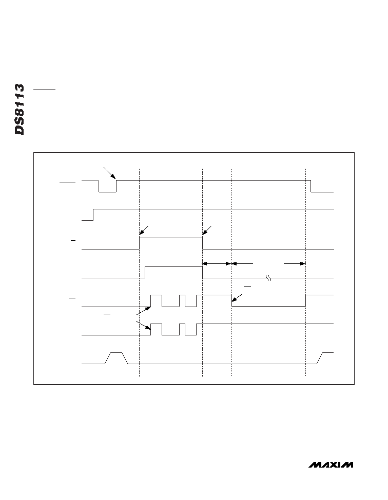 Stop Mode (Low-Power Mode) A low-power state, stop mode, can be entered by forc- ing the CMDVCC, 5V/3V, and 1_8V input pins to a logic-high state. Stop mode can only be entered when the smart card interface is inactive. In stop mode all internal analog circuits are disabled. The OFF pin fol- lows the status of the PRES pin. To exit stop mode, change the state of one or more of the three control pins to a logic-low. An internal 220µs (typ) power-up delay and the 8ms PRES debounce delay are in effect and OFF is asserted to allow the internal circuitry to sta- bilize. This prevents smart card access from occurring after leaving the stop mode. Figure 8 shows the control sequence for entering and exiting stop mode. Note that an in-progress deactivation sequence always finishes before the DS8113 enters low-power stop mode. Smart Card Interface 14 ______________________________________________________________________________________ CMDVCC 1_8V 5V/3V STOP MODE OFF PRES VCC DEACTIVATE INTERFACE ACTIVATE STOP MODE DEACTIVATE STOP MODE 220 µs DELAY OFF FOLLOWS PRES IN STOP MODE OFF ASSERTED TO WAIT FOR DELAY 8ms DEBOUNCE Figure 8. Stop-Mode Sequence |
|
|
Link URL |
| Does ALLDATASHEET help your business so far? [ DONATE ] |
About Alldatasheet | Advertisement | Contact us | Privacy Policy | Link to Datasheet | Link Exchange | Manufacturer List All Rights Reserved©Alldatasheet.com |
| Russian : Alldatasheetru.com | Korean : Alldatasheet.co.kr | Spanish : Alldatasheet.es | French : Alldatasheet.fr | Italian : Alldatasheetit.com Portuguese : Alldatasheetpt.com | Polish : Alldatasheet.pl | Vietnamese : Alldatasheet.vn Indian : Alldatasheet.in | Mexican : Alldatasheet.com.mx | British : Alldatasheet.co.uk | New Zealand : Alldatasheet.co.nz |
|
Family Site : ic2ic.com |
icmetro.com |
 Indian ▼
 English
 Chinese
 German
 Japanese
 Russian
 Korean
 Spanish
 French
 Italian
 Portuguese
 Polish
 Vietnamese
 Indian
 Mexican
 British
 New Zealand


