|
Electronic Components Datasheet Search |
|
|
Electronic Components Datasheet Search |
|
SP4306 Datasheet(PDF) 6 Page - SIPAT Co,Ltd |
|
|
|||||||||||||||||||||||||||||
SP4306 Datasheet(HTML) 6 Page - SIPAT Co,Ltd |
|
|
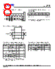
6 / 10 page 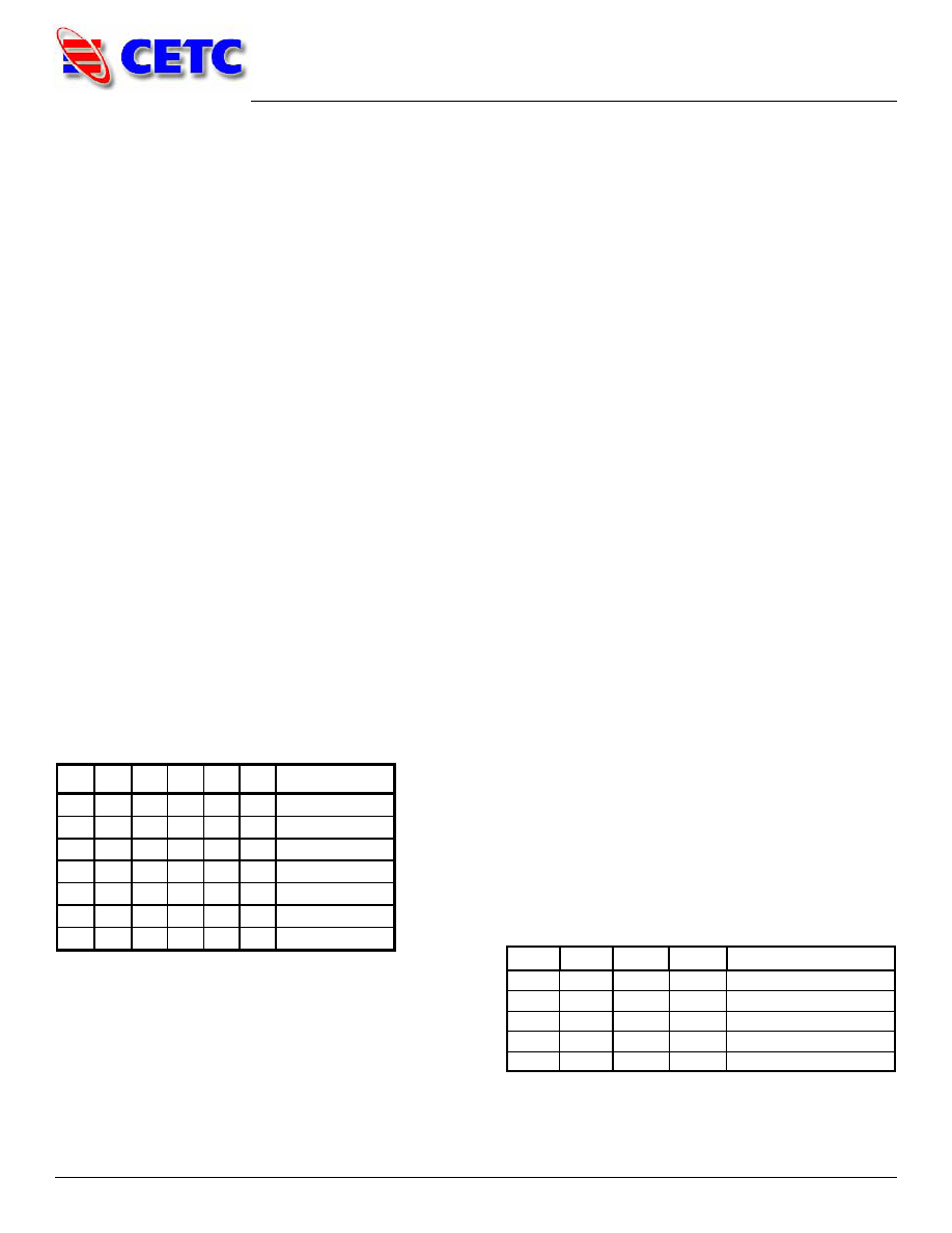 Product Specification SP4306 Page 6 of 10 Programming Options Parallel/Serial Selection Either a parallel or serial interface can be used to control the SP4306. The P/S bit provides this selection, with P/S=LOW selecting the parallel interface and P/S=HIGH selecting the serial interface. Parallel / Direct Mode Interface The parallel interface consists of five CMOS- compatible control lines that select the desired attenuation state, as shown in Table 5. The parallel interface timing requirements are defined by Figure 18 (Parallel Interface Timing Diagram), Table 9 (Parallel Interface AC Characteristics), and switching speed (Table 1). For parallel programming the Latch Enable (LE) should be held LOW while changing attenuation state control values, then pulse LE HIGH to LOW (per Figure 18) to latch new attenuation state into device. For direct programming, the Latch Enable (LE) line should be pulled HIGH. Changing attenuation state control values will change device state to new attenuation. Direct Mode is ideal for manual control of the device (using hardwire, switches, or jumpers). Table 5. Truth Table Serial Interface The SP4306’s serial interface is a 6-bit serial-in, parallel-out shift register buffered by a transparent latch. The latch is controlled by three CMOS- compatible signals: Data, Clock, and Latch Enable (LE). The Data and Clock inputs allow data to be serially entered into the shift register, a process that is independent of the state of the LE input. The LE input controls the latch. When LE is HIGH, the latch is transparent and the contents of the serial shift register control the attenuator. When LE is brought LOW, data in the shift register is latched. The shift register should be loaded while LE is held LOW to prevent the attenuator value from changing as data is entered. The LE input should then be toggled HIGH and brought LOW again, latching the new data. The stop bit (B0) of the data should always be low to prevent an unknown state in the device. The timing for this operation is defined by Figure 17 (Serial Interface Timing Diagram) and Table 8 (Serial Interface AC Characteristics). Power-up Control Settings The SP4306 always assumes a specifiable attenuation setting on power-up. This feature exists for both the Serial and Parallel modes of operation, and allows a known attenuation state to be established before an initial serial or parallel control word is provided. When the attenuator powers up in Serial mode (P/ S=1), the five control bits and a stop bit are set to whatever data is present on the five parallel data inputs (C1 to C16). This allows any one of the 32 attenuation settings to be specified as the power-up state. When the attenuator powers up in Parallel mode (P/ S=0) with LE=0, the control bits are automatically set to one of four possible values. These four values are selected by the two power-up control bits, PUP1 and PUP2, as shown in Table 6 (Power-Up Truth Table, Parallel Mode). Table 6. Power-Up Truth Table, Parallel Interface Mode Note: Power up with LE=1 provides normal parallel operation with C1-C16, and PUP1 and PUP2 are not active. P/S C16 C8 C4 C2 C1 Attenuation State 0 0 0 0 0 0 Reference Loss 0 0 0 0 0 1 1 dB 0 0 0 0 1 0 2 dB 0 0 0 1 0 0 4 dB 0 0 1 0 0 0 8 dB 0 1 0 0 0 0 16 dB 0 1 1 1 1 1 31 dB Note: Not all 32 possible combinations of C1-C16 are shown. P/S LE PUP2 PUP1 Attenuation State 0 0 0 0 Reference Loss 0 0 0 1 8 dB 0 0 1 0 16 dB 0 0 1 1 31 dB 0 1 X X Defined by C1-C16 Tel: +86-23-62808818 Fax: +86-23-62805284 www.sipatsaw.com / sawmkt@sipat.com |
|
|
Link URL |
| Does ALLDATASHEET help your business so far? [ DONATE ] |
About Alldatasheet | Advertisement | Contact us | Privacy Policy | Link to Datasheet | Link Exchange | Manufacturer List All Rights Reserved©Alldatasheet.com |
| Russian : Alldatasheetru.com | Korean : Alldatasheet.co.kr | Spanish : Alldatasheet.es | French : Alldatasheet.fr | Italian : Alldatasheetit.com Portuguese : Alldatasheetpt.com | Polish : Alldatasheet.pl | Vietnamese : Alldatasheet.vn Indian : Alldatasheet.in | Mexican : Alldatasheet.com.mx | British : Alldatasheet.co.uk | New Zealand : Alldatasheet.co.nz |
|
Family Site : ic2ic.com |
icmetro.com |
 Indian ▼
 English
 Chinese
 German
 Japanese
 Russian
 Korean
 Spanish
 French
 Italian
 Portuguese
 Polish
 Vietnamese
 Indian
 Mexican
 British
 New Zealand