|
Electronic Components Datasheet Search |
|
|
Electronic Components Datasheet Search |
|
MUL1-R4 Datasheet(PDF) 13 Page - ABB |
|
|
|||||||||||||||||||||||||||||
MUL1-R4 Datasheet(HTML) 13 Page - ABB |
|
|
13 / 28 page 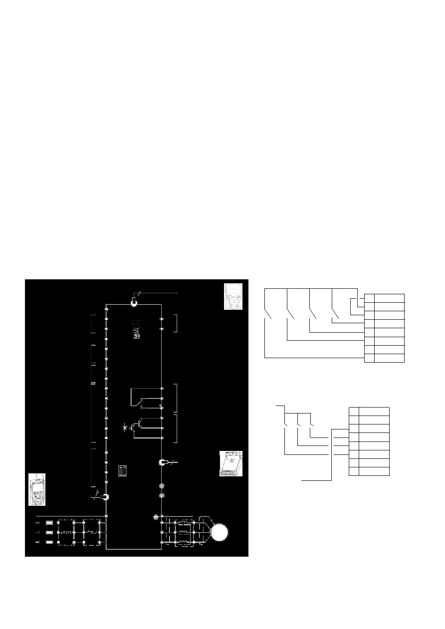 Typical I/O connections Catalog | ABB general purpose drives ACS310 13 Control connections Application macros Application macros are preprogrammed parameter sets. While starting up the drive, the user typically selects one of the macros that is best suited for the application. The diagram below gives an overview of ACS310 control connections and shows the default I/O connections for the ABB standard macro. − ABB standard macro − 3-wire macro − Alternative macro − Motor potentiometer − Hand/auto macro − PID control macro − PFC control macro − SPFC control macro − Modbus application macro SCR AI1 GND +10 V AI2 GND +24 V GND DCOM DI1 DI2 DI3 DI4 DI5 PE U1 V1 W1 AO GND ROCOM RONC RONO DOSRC DOOUT DOGND EMC VAR U2 V2 W2 Control panel (RJ-45) PE L1 L2 L3 AC motor M 3 ~ Analog output 0 to 20 mA PROGRAMMABLE RELAY AND DIGITAL OUTPUTS Relay output 250 V AC/30 V DC/6 A Digital/frequency output, PNP transistor type 30 V DC, max. 100 mA EMC filter grounding screw Varistor grounding screw Screen 8 Analog input 1 0 to 10 V Reference voltage +10 V DC, max 10 mA Analog input 2 Aux. voltage output +24 V DC, max. 200 mA PROGRAMMABLE DIGITAL INPUTS FlashDrop Modbus RTU (EIA-485) 3-phase power supply, 200 to 480 V AC Input choke Output choke EMC filter mA V Output relay module MREL-01 S1 1 2 3 4 5 6 9 10 11 12 13 14 15 16 23 24 25 26 SHIELD B A GND_A J701 6 DI5 can also be used as a frequency input 9 10 11 12 13 14 15 16 +24 V GND DCOM DI1 DI2 DI3 DI4 DI5 DI configuration PNP connected (source) with external power supply Const. speed 1 Fwd/ Rev Start/ Stop + 24 V 0 V ACS310: X1 DI configuration NPN connected (sink) +24 V GND DCOM DI1 DI2 DI3 DI4 DI5 9 10 11 12 13 14 15 16 ACS310: X1 Ramp pair sel Const. Speed 1 Fwd/ Rev Start/ Stop In addition to the standard macros, the user can create three user macros. The user macro allows the user to save the parameter settings for later use. The diagram below gives an overview of ACS310 control connections. Please refer to the ACS310 user’s manual for more detailed information. |
|
Link URL |
| Does ALLDATASHEET help your business so far? [ DONATE ] |
About Alldatasheet | Advertisement | Contact us | Privacy Policy | Link to Datasheet | Link Exchange | Manufacturer List All Rights Reserved©Alldatasheet.com |
| Russian : Alldatasheetru.com | Korean : Alldatasheet.co.kr | Spanish : Alldatasheet.es | French : Alldatasheet.fr | Italian : Alldatasheetit.com Portuguese : Alldatasheetpt.com | Polish : Alldatasheet.pl | Vietnamese : Alldatasheet.vn Indian : Alldatasheet.in | Mexican : Alldatasheet.com.mx | British : Alldatasheet.co.uk | New Zealand : Alldatasheet.co.nz |
|
Family Site : ic2ic.com |
icmetro.com |
 Indian ▼
 English
 Chinese
 German
 Japanese
 Russian
 Korean
 Spanish
 French
 Italian
 Portuguese
 Polish
 Vietnamese
 Indian
 Mexican
 British
 New Zealand