|
Electronic Components Datasheet Search |
|
|
Electronic Components Datasheet Search |
|
PIC18F1XK50 Datasheet(PDF) 52 Page - Microchip Technology |
|
|
|||||||||||||||||||||||||||||
PIC18F1XK50 Datasheet(HTML) 52 Page - Microchip Technology |
|
|
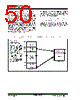
52 / 422 page  PIC18F/LF1XK50 DS41350D-page 52 Preliminary 2010 Microchip Technology Inc. FIGURE 4-2: TABLE WRITE OPERATION 4.2 Control Registers Several control registers are used in conjunction with the TBLRD and TBLWT instructions. These include the: • EECON1 register • EECON2 register • TABLAT register • TBLPTR registers 4.2.1 EECON1 AND EECON2 REGISTERS The EECON1 register (Register 4-1) is the control register for memory accesses. The EECON2 register is not a physical register; it is used exclusively in the memory write and erase sequences. Reading EECON2 will read all ‘0’s. The EEPGD control bit determines if the access will be a program or data EEPROM memory access. When EEPGD is clear, any subsequent operations will operate on the data EEPROM memory. When EEPGD is set, any subsequent operations will operate on the program memory. The CFGS control bit determines if the access will be to the Configuration/Calibration registers or to program memory/data EEPROM memory. When CFGS is set, subsequent operations will operate on Configuration registers regardless of EEPGD (see Section 24.0 “Special Features of the CPU”). When CFGS is clear, memory selection access is determined by EEPGD. The FREE bit allows the program memory erase oper- ation. When FREE is set, an erase operation is initiated on the next WR command. When FREE is clear, only writes are enabled. The WREN bit, when set, will allow a write operation. The WREN bit is clear on power-up. The WRERR bit is set by hardware when the WR bit is set and cleared when the internal programming timer expires and the write operation is complete. The WR control bit initiates write operations. The WR bit cannot be cleared, only set, by firmware. Then WR bit is cleared by hardware at the completion of the write operation. Table Pointer(1) Table Latch (8-bit) TBLPTRH TBLPTRL TABLAT Program Memory (TBLPTR<MSBs>) TBLPTRU Instruction: TBLWT* Note 1: During table writes the Table Pointer does not point directly to Program Memory. The LSBs of TBLPRTL actually point to an address within the write block holding registers. The MSBs of the Table Pointer deter- mine where the write block will eventually be written. The process for writing the holding registers to the program memory array is discussed in Section 4.5 “Writing to Flash Program Memory”. Holding Registers Program Memory Note: During normal operation, the WRERR is read as ‘1’. This can indicate that a write operation was prematurely terminated by a Reset, or a write operation was attempted improperly. Note: The EEIF interrupt flag bit of the PIR2 register is set when the write is complete. The EEIF flag stays set until cleared by firmware. |
|
Link URL |
| Does ALLDATASHEET help your business so far? [ DONATE ] |
About Alldatasheet | Advertisement | Contact us | Privacy Policy | Link to Datasheet | Link Exchange | Manufacturer List All Rights Reserved©Alldatasheet.com |
| Russian : Alldatasheetru.com | Korean : Alldatasheet.co.kr | Spanish : Alldatasheet.es | French : Alldatasheet.fr | Italian : Alldatasheetit.com Portuguese : Alldatasheetpt.com | Polish : Alldatasheet.pl | Vietnamese : Alldatasheet.vn Indian : Alldatasheet.in | Mexican : Alldatasheet.com.mx | British : Alldatasheet.co.uk | New Zealand : Alldatasheet.co.nz |
|
Family Site : ic2ic.com |
icmetro.com |
 Indian ▼
 English
 Chinese
 German
 Japanese
 Russian
 Korean
 Spanish
 French
 Italian
 Portuguese
 Polish
 Vietnamese
 Indian
 Mexican
 British
 New Zealand