 |
Electronic Components Datasheet Search |
|
|
Electronic Components Datasheet Search |
|
ADRF6755ACPZ-R7 Datasheet(PDF) 27 Page - Analog Devices |
|
|
|||||||||||||||||||||||||||||
ADRF6755ACPZ-R7 Datasheet(HTML) 27 Page - Analog Devices |
|
|
27 / 48 page 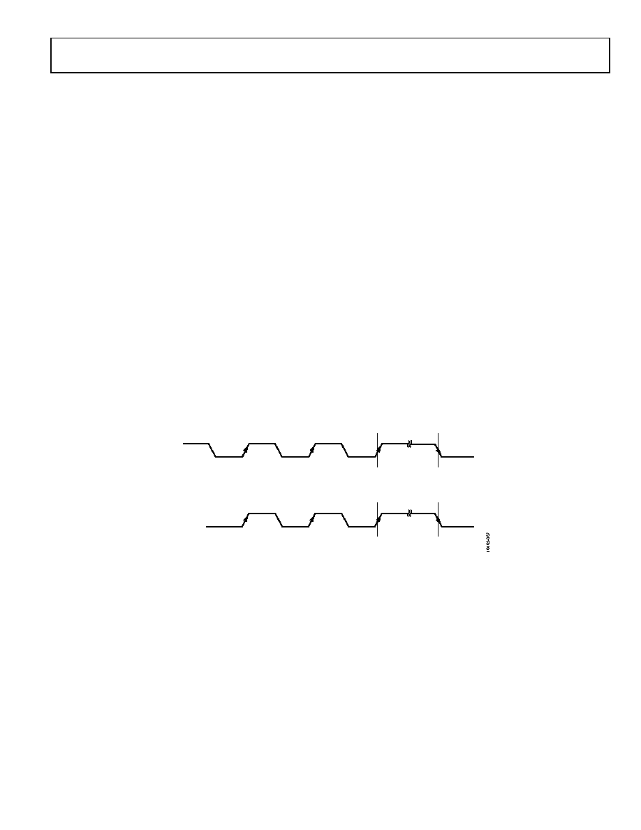 Data Sheet ADRF6755 Rev. B | Page 27 of 48 SPI INTERFACE The ADRF6755 also supports the SPI protocol. The part powers up in I2C mode but is not locked in this mode. To stay in I2C mode, it is recommended that the user tie the CS line to either 3.3 V or GND, thus disabling SPI mode. It is not possible to lock the I2C mode, but it is possible to select and lock the SPI mode. To select and lock the SPI mode, three pulses must be sent to the CS pin, as shown in Figure 67. When the SPI protocol is locked in, it cannot be unlocked while the device is still powered up. To reset the serial interface, the part must be powered down and powered up again. Serial Interface Selection The CS pin controls selection of the I2C or SPI interface. Figure 67 shows the selection process that is required to lock the SPI mode. To communicate with the part using the SPI protocol, three pulses must be sent to the CS pin. On the third rising edge, the part selects and locks the SPI protocol. Consistent with most SPI standards, the CS pin must be held low during all SPI communication to the part and held high at all other times. SPI Serial Interface Functionality The SPI serial interface of the ADRF6755 consists of the CS, SDI (SDI/SDA), CLK (CLK/SCL), and SDO pins. CS is used to select the device when more than one device is connected to the serial clock and data lines. CLK is used to clock data in and out of the part. The SDI pin is used to write to the registers. The SDO pin is a dedicated output for the read mode. The part operates in slave mode and requires an externally applied serial clock to the CLK pin. The serial interface is designed to allow the part to be interfaced to systems that provide a serial clock that is synchronized to the serial data. Figure 68 shows an example of a write operation to the ADRF6755. Data is clocked into the registers on the rising edge of CLK using a 24-bit write command. The first eight bits represent the write command, 0xD4; the next eight bits are the register address; and the final eight bits are the data to be written to the specific register. Figure 69 shows an example of a read operation. In this example, a shortened 16-bit write command is first used to select the appropriate register for a read operation, the first eight bits representing the write command, 0xD4, and the final eight bits representing the specific register. Then the CS line is pulsed low for a second time to retrieve data from the selected register using a 16-bit read command, the first eight bits representing the read command, 0xD5, and the final eight bits representing the contents of the register being read. Figure 3 shows the timing for both SPI read and SPI write operations. Figure 67. Selecting the SPI Protocol SPI LOCKED ON THIRD RISING EDGE SPI FRAMING EDGE C B A SPI LOCKED ON THIRD RISING EDGE SPI FRAMING EDGE C B A CS (STARTING HIGH) CS (STARTING LOW) |
|
Link URL |
| Does ALLDATASHEET help your business so far? [ DONATE ] |
About Alldatasheet | Advertisement | Contact us | Privacy Policy | Link to Datasheet | Link Exchange | Manufacturer List All Rights Reserved©Alldatasheet.com |
| Russian : Alldatasheetru.com | Korean : Alldatasheet.co.kr | Spanish : Alldatasheet.es | French : Alldatasheet.fr | Italian : Alldatasheetit.com Portuguese : Alldatasheetpt.com | Polish : Alldatasheet.pl | Vietnamese : Alldatasheet.vn Indian : Alldatasheet.in | Mexican : Alldatasheet.com.mx | British : Alldatasheet.co.uk | New Zealand : Alldatasheet.co.nz |
|
Family Site : ic2ic.com |
icmetro.com |
 Indian ▼
 English
 Chinese
 German
 Japanese
 Russian
 Korean
 Spanish
 French
 Italian
 Portuguese
 Polish
 Vietnamese
 Indian
 Mexican
 British
 New Zealand


