 |
Electronic Components Datasheet Search |
|
|
Electronic Components Datasheet Search |
|
ADRF6755ACPZ-R7 Datasheet(PDF) 23 Page - Analog Devices |
|
|
|||||||||||||||||||||||||||||
ADRF6755ACPZ-R7 Datasheet(HTML) 23 Page - Analog Devices |
|
|
23 / 48 page 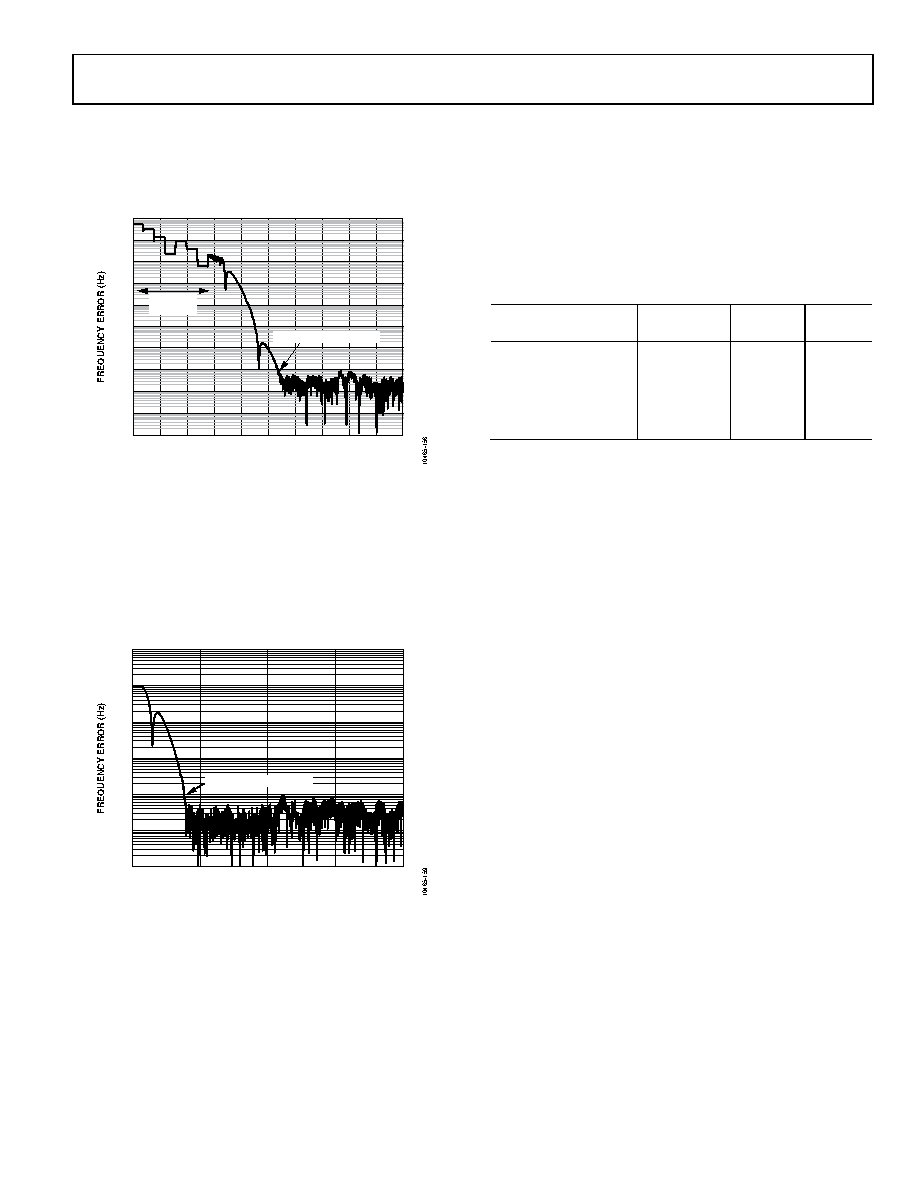 Data Sheet ADRF6755 Rev. B | Page 23 of 48 Note that BSCDIV must be recalculated if the PFD frequency is changed. The recommended autocalibration setting is 70 µs. During this time, the VCO VTUNE is disconnected from the output of the loop filter and is connected to an internal reference voltage. A typical frequency acquisition is shown in Figure 58. Figure 58. PLL Acquisition After autocalibration, normal PLL action resumes, and the correct frequency is acquired to within a frequency error of 100 Hz in 170 μs typically. For a maximum cumulative step of 100 kHz/2RFDIV, autocalibration can be turned off by setting Register CR24, Bit 0 = 1. This enables cumulative PLL acquisi- tions of ≤100 kHz (for RFDIV = ÷1, 50 kHz for RFDIV = ÷2, and so on) to occur without the autocalibration procedure, which improves acquisition times significantly (see Figure 59). Figure 59. PLL Acquisition Without Autocalibration for a 100 kHz Step Programming the Correct LO Frequency There are two steps to programming the correct LO frequency. The user must calculate the RFDIV value based on the required LO frequency and PFD frequency, and the N-divider ratio that is required in the PLL. 1. Calculate the value of RFDIV, which is used to program Register CR28, Bits[2:0] and CR27, Bit 4 from the following lookup table, Table 6. Table 6. RFDIV Lookup Table LO Frequency (MHz) RFDIVIDER CR28[2:0] = RFDIV CR27[4] 1155 < LO < 2400 Divide-by-1 000 1 577.5 < LO ≤ 1155 Divide-by-2 001 0 288.75 < LO ≤ 577.5 Divide-by-4 010 0 144.375 < LO ≤ 288.75 Divide-by-8 011 0 100 < LO ≤ 144.375 Divide-by-16 100 0 2. Using the following equation, calculate the value of the N-divider: N = (2RFDIV × LO)/fPFD (4) where: N is the N-divider value. RFDIV is the setting in Register CR28, Bits[2:0]. LO is the local oscillator frequency. fPFD is the PFD frequency. This equation is a different representation of Equation 2. Example to Program the Correct LO Frequency Assume that the PFD frequency is 40 MHz and that the required LO frequency is 1875 MHz. From Table 6, 2RFDIV = 1 (RFDIV = 0) N = (1 × 1875 × 106)/(40 × 106) = 46.875 The N-divider value is composed of integer (INT) and fractional (FRAC) components according to the following equation: N = INT + FRAC/225 (5) INT = 46 and FRAC = 29,360,128 The appropriate registers must then be programmed according to the register map. The order in which the registers are programmed is important. Writing to CR0 initiates a PLL acquisition cycle. If the programmed LO frequency requires a change in the value of CR27[4] (see Table 6), CR27 should be the last register programmed, preceded by CR0. If the programmed LO frequency does not require a change in the value of CR27[4], it is optional to omit the write to CR27 and, in that case, CR0 should be the last register programmed. 0.1 1 10 100 1k 10k 100k 1M 10M 100M 1G 0 25 50 75 100 125 150 175 200 225 250 TIME (µs) AUTOCAL TIME (μs) ACQUISITION TO 100Hz 1 10 100 1k 10k 100k 1M 0 50 100 150 200 TIME (μs) ACQUISITION TO 100Hz |
|
Link URL |
| Does ALLDATASHEET help your business so far? [ DONATE ] |
About Alldatasheet | Advertisement | Contact us | Privacy Policy | Link to Datasheet | Link Exchange | Manufacturer List All Rights Reserved©Alldatasheet.com |
| Russian : Alldatasheetru.com | Korean : Alldatasheet.co.kr | Spanish : Alldatasheet.es | French : Alldatasheet.fr | Italian : Alldatasheetit.com Portuguese : Alldatasheetpt.com | Polish : Alldatasheet.pl | Vietnamese : Alldatasheet.vn Indian : Alldatasheet.in | Mexican : Alldatasheet.com.mx | British : Alldatasheet.co.uk | New Zealand : Alldatasheet.co.nz |
|
Family Site : ic2ic.com |
icmetro.com |
 Indian ▼
 English
 Chinese
 German
 Japanese
 Russian
 Korean
 Spanish
 French
 Italian
 Portuguese
 Polish
 Vietnamese
 Indian
 Mexican
 British
 New Zealand


