 |
Electronic Components Datasheet Search |
|
|
Electronic Components Datasheet Search |
|
XIO2000 Datasheet(PDF) 27 Page - Texas Instruments |
|
|
|||||||||||||||||||||||||||||
XIO2000 Datasheet(HTML) 27 Page - Texas Instruments |
|
|
27 / 150 page 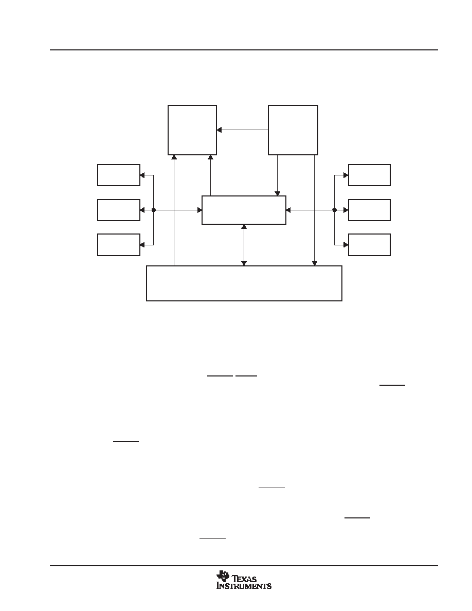 Feature/Protocol Descriptions 15 November 2005 SCPS097B 3 Feature/Protocol Descriptions This chapter provides a high-level overview of all significant device features. Figure 3−1 shows a simplified block diagram of the basic architecture of the PCI-Express to PCI Bridge. The top of the diagram is the PCI Express interface and the PCI bus interface is located at the bottom of the diagram. PCI Express Transmitter PCI Express Receiver PCI Bus Interface Configuration and Memory Register GPIO Serial EEPROM Serial IRQ Reset Controller Clock Generator Power Mgmt Figure 3−1. XIO2000 Block Diagram 3.1 Power-Up/-Down Sequencing The bridge contains both 1.5-V and 3.3-V power terminals. In addition, a VAUX supply exists to support the D3cold state. The clamping voltage (VCCP) can be either 3.3-V or 5.0-V, depending on the PCI bus interface requirements. The following power-up and power-down sequences describe how power is applied to these terminals. In addition, the bridge has three resets: PERST, GRST, and an internal power-on reset. These resets are fully described in Section 3.2. The following power-up and power-down sequences describe how PERST is applied to the bridge. The application of the PCI Express reference clock (REFCLK) is important to the power-up/-down sequence and is included in the following power-up and power-down descriptions. 3.1.1 Power-Up Sequence 1. Assert PERST to the device. 2. Apply 1.5-V and 3.3-V voltages. 3. Apply VCCP clamp voltage. 4. Apply a stable PCI Express reference clock. 5. To meet PCI Express specification requirements, PERST cannot be deasserted until the following two delay requirements are satisfied: − Wait a minimum of 100 µs after applying a stable PCI Express reference clock. The 100-µs limit satisfies the requirement for stable device clocks by the deassertion of PERST. − Wait a minimum of 100 ms after applying power. The 100-ms limit satisfies the requirement for stable power by the deassertion of PERST. |
|
Link URL |
| Does ALLDATASHEET help your business so far? [ DONATE ] |
About Alldatasheet | Advertisement | Contact us | Privacy Policy | Link to Datasheet | Link Exchange | Manufacturer List All Rights Reserved©Alldatasheet.com |
| Russian : Alldatasheetru.com | Korean : Alldatasheet.co.kr | Spanish : Alldatasheet.es | French : Alldatasheet.fr | Italian : Alldatasheetit.com Portuguese : Alldatasheetpt.com | Polish : Alldatasheet.pl | Vietnamese : Alldatasheet.vn Indian : Alldatasheet.in | Mexican : Alldatasheet.com.mx | British : Alldatasheet.co.uk | New Zealand : Alldatasheet.co.nz |
|
Family Site : ic2ic.com |
icmetro.com |
 Indian ▼
 English
 Chinese
 German
 Japanese
 Russian
 Korean
 Spanish
 French
 Italian
 Portuguese
 Polish
 Vietnamese
 Indian
 Mexican
 British
 New Zealand


