|
Electronic Components Datasheet Search |
|
|
Electronic Components Datasheet Search |
|
AD8342ACPZ-R2 Datasheet(PDF) 5 Page - Analog Devices |
|
|
|||||||||||||||||||||||||||||
AD8342ACPZ-R2 Datasheet(HTML) 5 Page - Analog Devices |
|
|
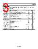
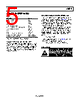
5 / 25 page 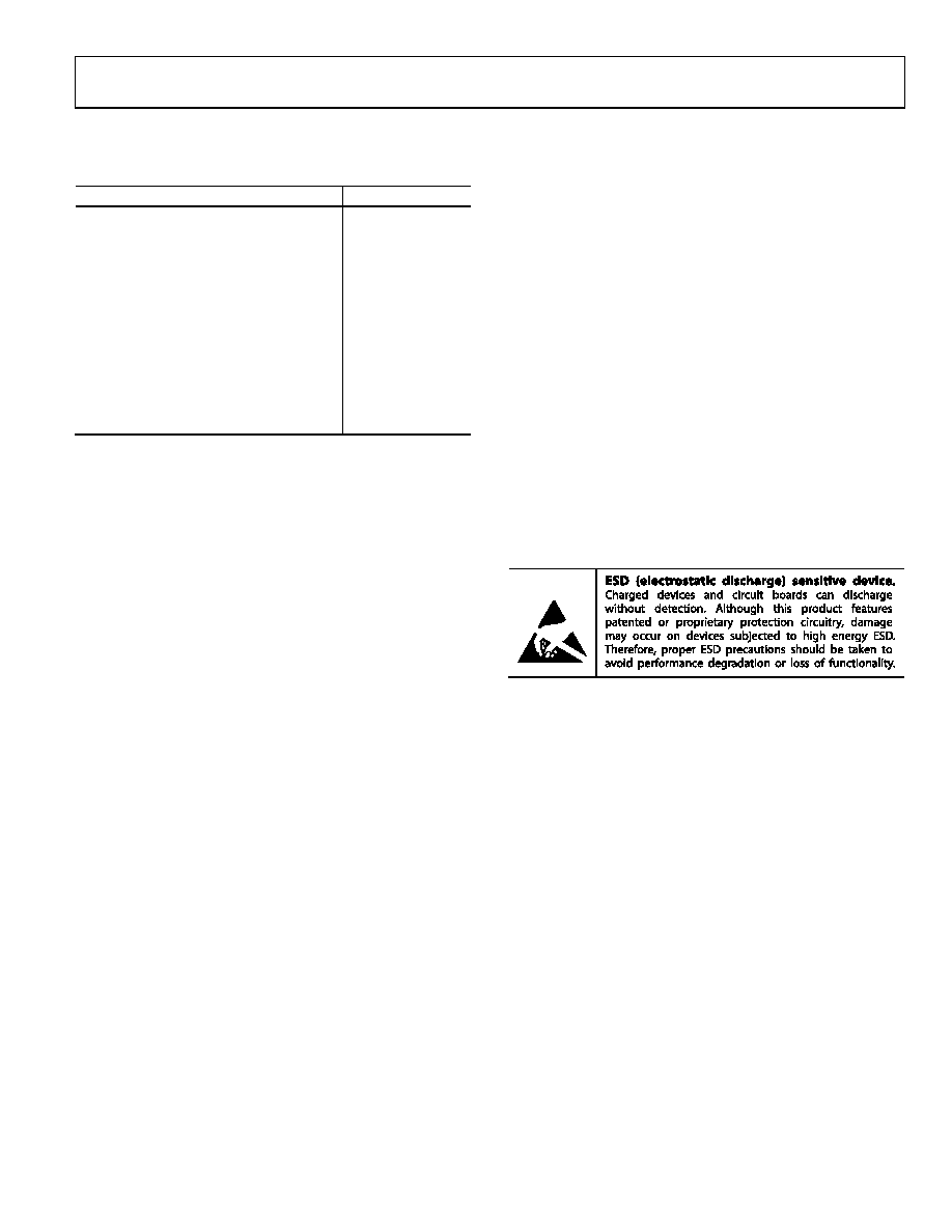 Data Sheet AD8342 Rev. C | Page 5 of 25 ABSOLUTE MAXIMUM RATINGS Table 3. Parameter Rating Supply Voltage, VS 5.5 V RF Input Level 12 dBm LO Input Level 12 dBm PWDN Pin VS + 0.5 V IFOP, IFOM Bias Voltage 5.5 V Minimum Resistor from EXRB to COMM 1.8 kΩ Internal Power Dissipation 650 mW θJA1 77°C/W θJB1 37.4°C/W Maximum Junction Temperature 135°C Operating Temperature Range −40°C to +85°C Storage Temperature Range −65°C to +150°C 1 Measured using a JESD51-7 printed circuit board (PCB). Stresses at or above those listed under Absolute Maximum Ratings may cause permanent damage to the product. This is a stress rating only; functional operation of the product at these or any other conditions above those indicated in the operational section of this specification is not implied. Operation beyond the maximum operating conditions for extended periods may affect product reliability. JUNCTION TO BOARD THERMAL IMPEDANCE The junction to board thermal impedance (θJB) is the thermal impedance from the die to the leads of the AD8342. The value given in Table 3 is based on the standard PCB described in JESD51-7 for the thermal testing of a surface-mount component. Board size and complexity (number of layers) affect θJB; more layers tend to reduce thermal impedance slightly. If the board temperature is known, use the junction to board thermal impedance to calculate the die temperature (also known as the junction temperature) to ensure that it does not exceed the specified limit of 135°C. For example, if the board temperature is 85°C, the die temperature is given by the equation, ( ) JB DISS B J P T T θ × + = The worst case power dissipation for the AD8342 is 593 mW (5.25 V × 113 mA, see Table 1). Therefore, TJ is ( ) C 2 . 107 C/W 4 . 37 W 593 . 0 C 85 ° = ° × + ° = J T ESD CAUTION |
|
|
Link URL |
| Does ALLDATASHEET help your business so far? [ DONATE ] |
About Alldatasheet | Advertisement | Contact us | Privacy Policy | Link to Datasheet | Link Exchange | Manufacturer List All Rights Reserved©Alldatasheet.com |
| Russian : Alldatasheetru.com | Korean : Alldatasheet.co.kr | Spanish : Alldatasheet.es | French : Alldatasheet.fr | Italian : Alldatasheetit.com Portuguese : Alldatasheetpt.com | Polish : Alldatasheet.pl | Vietnamese : Alldatasheet.vn Indian : Alldatasheet.in | Mexican : Alldatasheet.com.mx | British : Alldatasheet.co.uk | New Zealand : Alldatasheet.co.nz |
|
Family Site : ic2ic.com |
icmetro.com |
 Indian ▼
 English
 Chinese
 German
 Japanese
 Russian
 Korean
 Spanish
 French
 Italian
 Portuguese
 Polish
 Vietnamese
 Indian
 Mexican
 British
 New Zealand