|
Electronic Components Datasheet Search |
|
|
Electronic Components Datasheet Search |
|
AD8342ACPZ-R2 Datasheet(PDF) 18 Page - Analog Devices |
|
|
|||||||||||||||||||||||||||||
AD8342ACPZ-R2 Datasheet(HTML) 18 Page - Analog Devices |
|
|
18 / 25 page 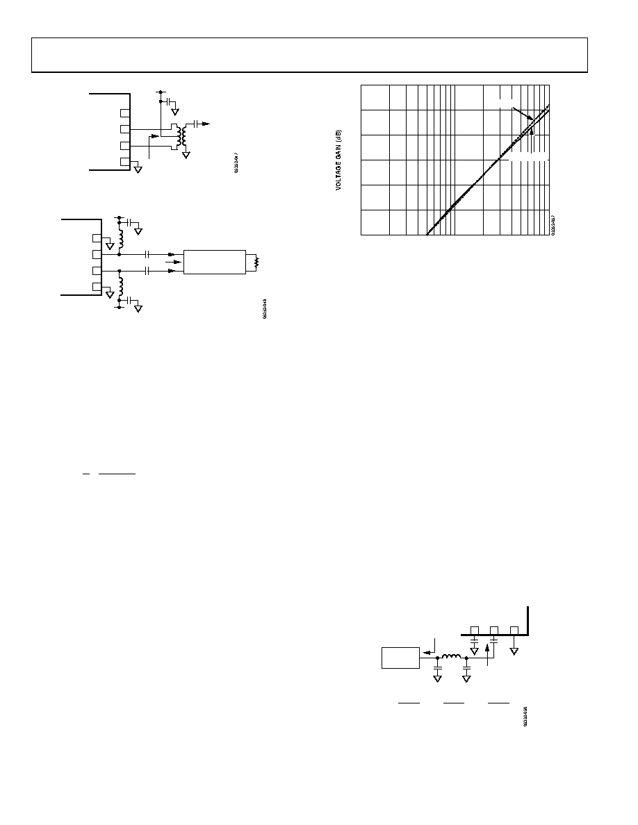 AD8342 Data Sheet Rev. C | Page 18 of 25 COMM 8 IFOP 7 IFOM 6 COMM 5 AD8342 ZL = 100Ω IF OUT ZO = 50Ω +VS 2:1 Figure 47. Biasing the IF Port Open-Collector Outputs Using a Center-Tapped Impedance Transformer COMM 8 IFOP 7 IFOM 6 COMM 5 AD8342 RFC +VS RFC ZL = 100Ω IF OUT+ IF OUT– +VS ZL IMPEDANCE TRANSFORMING NETWORK Figure 48. Biasing the IF Port Open-Collector Outputs Using Pull-Up Choke Inductors The AD8342 is optimized for driving a 100 Ω load. Although the device is capable of driving a wide variety of loads, to maintain optimum distortion and noise performance, it is advised that the presented load at the IF outputs is close to 100 Ω. The linear differential voltage conversion gain of the mixer can be modeled as AV = Gm × RLOAD where: e m m m R g g G 1 1 RLOAD is the single-ended load impedance. gm is the transistor transconductance and is equal to 1810/RBIAS. Re = 15 Ω. The external RBIAS resistor controls the power dissipation and dynamic range of the AD8342. Because the AD8342 has internal resistive degeneration, the conversion gain is primarily determined by the load impedance and the on-chip degeneration resistors. Figure 49 shows how gain varies with IF load. The external RBIAS resistor has only a small effect. The most direct way to affect conversion gain is by varying the load impedance. Small loads result in lower gains while larger loads increase the conversion gain. If the IF load impedance is too large, it causes a decrease in linearity (P1dB, IP3). To maintain positive conversion gain and preserve SFDR performance, the differential load presented at the IF port must remain in the range of about 100 Ω to 250 Ω. 30 0 10 1000 IF LOAD (Ω) 100 25 20 15 10 5 MEASURED MODELED Figure 49. Voltage Conversion Gain vs. IF Loading LO CONSIDERATIONS The LOIN port provides a 50 Ω load impedance with common- mode decoupling on LOCM. Again, common-grade ceramic capacitors provide sufficient signal coupling and bypassing of the LO interface. The LO signal must have adequate phase noise characteristics and low second harmonic content to prevent degradation of the noise figure performance of the AD8342. An LO plagued with poor phase noise can result in reciprocal mixing, a mechanism that causes spectral spreading of the downconverted signal, limiting the sensitivity of the mixer at frequencies adjacent to any large input signals. The internal LO buffer provides enough gain to hard-limit the input LO and provide fast switching of the mixer core. Odd harmonic content present on the LO drive signal does not impact mixer performance; however, even-order harmonics cause the mixer core to commutate in an unbalanced manner, potentially degrading noise performance. Simple lumped element low-pass filtering can be applied to help reject the harmon- ic content of a given local oscillator, as shown in Figure 50. The filter depicted is a common 3-pole Chebyshev, designed to maintain a 1-to-1 source-to-load impedance ratio with no more than 0.5 dB of ripple in the pass band. Other filter structures can be effective as long as the second harmonic of the LO is filtered to negligible levels, for example, ~30 dB below the fundamental. AD8342 LOIN 3 COMM 4 LOCM 2 RL FOR RS = RL fC - FILTER CUTOFF FREQUENCY RS C1 C3 LO SOURCE L2 C1 = 1.864 2π fcRL C3 = 1.834 2π fcRL L2 = 1.28RL 2π fc Figure 50. Using a Low-Pass Filter to Reduce LO Second Harmonic |
|
|
Link URL |
| Does ALLDATASHEET help your business so far? [ DONATE ] |
About Alldatasheet | Advertisement | Contact us | Privacy Policy | Link to Datasheet | Link Exchange | Manufacturer List All Rights Reserved©Alldatasheet.com |
| Russian : Alldatasheetru.com | Korean : Alldatasheet.co.kr | Spanish : Alldatasheet.es | French : Alldatasheet.fr | Italian : Alldatasheetit.com Portuguese : Alldatasheetpt.com | Polish : Alldatasheet.pl | Vietnamese : Alldatasheet.vn Indian : Alldatasheet.in | Mexican : Alldatasheet.com.mx | British : Alldatasheet.co.uk | New Zealand : Alldatasheet.co.nz |
|
Family Site : ic2ic.com |
icmetro.com |
 Indian ▼
 English
 Chinese
 German
 Japanese
 Russian
 Korean
 Spanish
 French
 Italian
 Portuguese
 Polish
 Vietnamese
 Indian
 Mexican
 British
 New Zealand