|
Electronic Components Datasheet Search |
|
|
Electronic Components Datasheet Search |
|
AD8342ACPZ-R2 Datasheet(PDF) 19 Page - Analog Devices |
|
|
|||||||||||||||||||||||||||||
AD8342ACPZ-R2 Datasheet(HTML) 19 Page - Analog Devices |
|
|
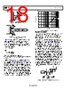
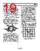
19 / 25 page 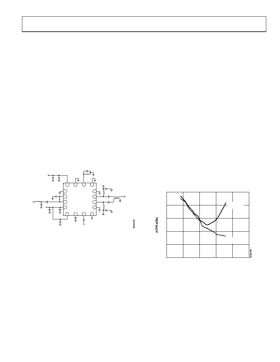 Data Sheet AD8342 Rev. C | Page 19 of 25 HIGH FREQUENCY APPLICATIONS The AD8342 is a broadband mixer capable of both up and down conversion. Unlike other mixers that rely on on-chip reactive circuitry to optimize performance over a specific band, the AD8342 is a versatile general-purpose device that can be used from arbitrarily low frequencies to several GHz. In general, the following considerations help ensure optimum performance: • Minimize the ac loading impedance of IF port bias network. • Maximize the power transfer to the desired ac load. • For the maximum conversion gain and the lowest noise performance, reactively match the input as described in the IF Port section. • For the maximum input compression point and input intercept points, resistively terminate the input as described in the IF Port section. As an example, Figure 51 shows the AD8342 as an up- converting mixer for a W-CDMA single-carrier transmitter design. For this application, it was desirable to achieve −65 dBc adjacent channel power ratio (ACPR) at a −13 dBm output power level. The ACPR is a measure of both distortion and noise carried into an adjacent frequency channel due to the finite intercept points and noise figure of an active device. 8 7 6 13 15 16 COMM IFOP IFOM 5 COMM 14 2 1 3 4 COMM RFCM RFIN VPMX VPDC PWDN EXRB COMM 11 12 10 9 VPLO LOCM LOIN COMM AD8342 VPOS VPOS 34nH 34nH 100pF 100pF 1nF 1nF ETC1-1-13 100pF 100pF 0.1µF VPOS 1nF 1nF 1970MHz OSC 1.82k Ω 100pF 4.7pF 170MHz INPUT 100nH 1nF 499 Ω VPOS 100pF 0.1pF 2140MHz OUT 1nF Figure 51. W-CDMA Tx Upconversion Application Circuit Because a W-CDMA channel encompasses a bandwidth of almost 5 MHz, it is necessary to keep the Q of the matching circuit low enough so that phase and magnitude variations are below an acceptable level over the 5 MHz band. It is possible to use purely reactive matching to transform a 50 Ω source to match the raw ~1 kΩ input impedance of the AD8342. However, the L and C component variations can present production concerns due to the sensitivity of the match. For this application, it is advantageous to reduce the ~1 kΩ input impedance using an external shunt termination resistor to allow a lower Q reactive matching network. In Figure 52, the input is terminated across the RFIN and RFCM pins using a 499 Ω termination. The termination must be as close to the device as possible to minimize standing wave concerns. The RFCM is bypassed to ground using a 1 nF capacitor. A dc blocking capacitor of 1 nF is used to isolate the dc input voltage present on the RFIN pin from the source. A step-up impedance transformation is realized using a series L shunt C reactive network. The actual values used must accommodate for the series L and stray C parasitics of the connecting transmission line segments. When using the customer evaluation board with the components specified in Figure 51, the return loss over a 5 MHz band centered at 170 MHz was better than 10 dB. External pull-up choke inductors feed dc bias into the open- collector outputs. It is desirable to select pull-up choke inductors that present high loading reactance at the output frequency. Coilcraft 0302CS series inductors were selected due to their very high self resonant frequency and Q. A 1:1 balun was ac-coupled to the output to convert the differential output to a single-ended signal and present the output with a 50 Ω ac loading impedance. The performance of the circuit is shown in Figure 52. The average ACPR of the adjacent and alternate channels is presented vs. output power. The circuit provides a 65 dBc ACPR at −13 dBm output power. The optimum ACPR power level can be shifted to the right or left by adjusting the output loading and the loss of the input match. –60 –70 –25 0 OUTPUT POWER (dBm) –62 –64 –66 –68 –20 –15 –10 –5 ADJACENT CHANNELS ALTERNATE CHANNELS Figure 52. Single Carrier W-CDMA ACPR Performance of Tx Upconversion Circuit (Test Model 1_64) |
|
|
Link URL |
| Does ALLDATASHEET help your business so far? [ DONATE ] |
About Alldatasheet | Advertisement | Contact us | Privacy Policy | Link to Datasheet | Link Exchange | Manufacturer List All Rights Reserved©Alldatasheet.com |
| Russian : Alldatasheetru.com | Korean : Alldatasheet.co.kr | Spanish : Alldatasheet.es | French : Alldatasheet.fr | Italian : Alldatasheetit.com Portuguese : Alldatasheetpt.com | Polish : Alldatasheet.pl | Vietnamese : Alldatasheet.vn Indian : Alldatasheet.in | Mexican : Alldatasheet.com.mx | British : Alldatasheet.co.uk | New Zealand : Alldatasheet.co.nz |
|
Family Site : ic2ic.com |
icmetro.com |
 Indian ▼
 English
 Chinese
 German
 Japanese
 Russian
 Korean
 Spanish
 French
 Italian
 Portuguese
 Polish
 Vietnamese
 Indian
 Mexican
 British
 New Zealand