|
Electronic Components Datasheet Search |
|
|
Electronic Components Datasheet Search |
|
AD8342ACPZ-R2 Datasheet(PDF) 17 Page - Analog Devices |
|
|
|||||||||||||||||||||||||||||
AD8342ACPZ-R2 Datasheet(HTML) 17 Page - Analog Devices |
|
|
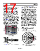
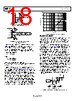
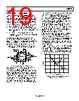
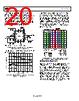
17 / 25 page 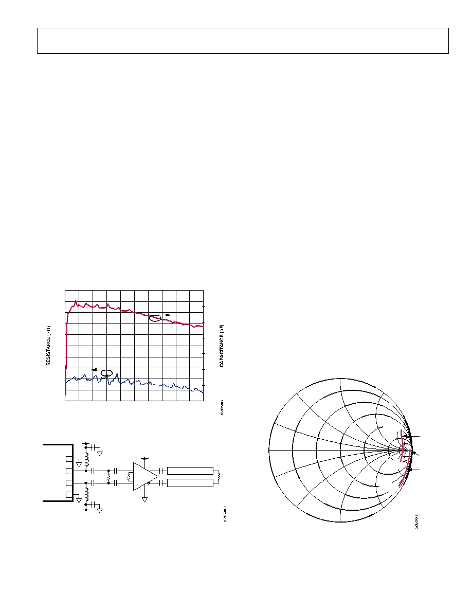 Data Sheet AD8342 Rev. C | Page 17 of 25 IF PORT The IF port comprises open-collector differential outputs. The NPN open-collectors can be modeled as current sources that are shunted with resistances of ~10 kΩ in parallel with capacitances of ~1 pF. The specified performance numbers for the AD8342 were measured with 100 Ω differential terminations. However, different load impedances can be used where circumstances dictate. In general, lower load impedances result in lower conversion gain and lower output P1dB. Higher load imped- ances result in higher conversion gain for small signals, but lower IP3 values for both input and output. If the IF signal is to be delivered to a remote load, more than a few millimeters away at high output frequencies, avoid unintended parasitic effects due to the intervening PCB traces. One approach is to use an impedance transforming network or transformer located close to the AD8342. If very wideband output is desired, a nearby buffer amplifier may be a better choice, especially if IF response to dc is required. An example of such a circuit is presented in Figure 45, in which the AD8351 differential amplifier is used to drive a pair of 75 Ω transmission lines. The gain of the buffer can be independently set by appropriate choice of the value for the gain resistor, RG. 50 0.5 0 0 1G FREQUENCY (Hz) 45 0.4 40 0.3 35 0.2 30 0.1 25 0 20 –0.1 15 –0.2 10 5 100M 200M 300M 400M 500M 600M 700M 800M 900M Figure 44. IF Port Impedance COMM 8 IFOP 7 IFOM 6 COMM 5 AD8342 AD8351 + – RFC +VS RFC ZL = 100Ω +VS +VS 100Ω RG ZL Tx LINE ZO = 75Ω Tx LINE ZO = 75Ω Figure 45. AD8351 Used as Transmission Line Driver and Impedance Buffer The high input impedance of the AD8351 allows a shunt differential termination to provide the desired 100 Ω load to the AD8342 IF output port. It is necessary to bias the open-collector outputs using one of the schemes presented in Figure 47 and Figure 48. Figure 47 illustrates the application of a center-tapped impedance transform- er. The turn ratio of the transformer must be selected to provide the desired impedance transformation. In the case of a 50 Ω load impedance, use a 2-to-1 impedance ratio transformer to transform the 50 Ω load into a 100 Ω differential load at the IF output pins. Figure 48 illustrates a differential IF interface where pull-up choke inductors are used to bias the open-collector outputs. The shunting impedance of the choke inductors used to couple dc current into the mixer core must be large enough at the IF operating frequency so it does not load down the output current before reaching the intended load. Additionally, the dc current handling capability of the selected choke inductors must be at least 45 mA. The self-resonant frequency of the selected choke must be higher than the intended IF frequency. A variety of suitable choke inductors is commercially available from manufacturers such as Murata and Coilcraft®. Figure 46 shows the loading effects when using nonideal inductors. An impedance transforming network may be required to transform the final load impedance to 100 Ω at the IF outputs. There are several good reference books that explain general impedance matching procedures, including: • Chris Bowick, RF Circuit Design, Newnes, Reprint Edition, 1997. • David M. Pozar, Microwave Engineering, Wiley, Third Edition, 2004. • Guillermo Gonzalez, Microwave Transistor Amplifiers: Analysis and Design, Prentice Hall, Second Edition, 1996. 0 180 30 330 50MHz 50MHz 500MHz 500MHz 60 90 270 300 120 240 150 210 REAL CHOKES IDEAL CHOKES Figure 46. IF Port Loading Effects Due to Finite Q Pull-Up Inductors (Murata BLM18HD601SN1D Chokes) |
|
|
Link URL |
| Does ALLDATASHEET help your business so far? [ DONATE ] |
About Alldatasheet | Advertisement | Contact us | Privacy Policy | Link to Datasheet | Link Exchange | Manufacturer List All Rights Reserved©Alldatasheet.com |
| Russian : Alldatasheetru.com | Korean : Alldatasheet.co.kr | Spanish : Alldatasheet.es | French : Alldatasheet.fr | Italian : Alldatasheetit.com Portuguese : Alldatasheetpt.com | Polish : Alldatasheet.pl | Vietnamese : Alldatasheet.vn Indian : Alldatasheet.in | Mexican : Alldatasheet.com.mx | British : Alldatasheet.co.uk | New Zealand : Alldatasheet.co.nz |
|
Family Site : ic2ic.com |
icmetro.com |
 Indian ▼
 English
 Chinese
 German
 Japanese
 Russian
 Korean
 Spanish
 French
 Italian
 Portuguese
 Polish
 Vietnamese
 Indian
 Mexican
 British
 New Zealand