|
Electronic Components Datasheet Search |
|
|
Electronic Components Datasheet Search |
|
AD8342ACPZ-R2 Datasheet(PDF) 6 Page - Analog Devices |
|
|
|||||||||||||||||||||||||||||
AD8342ACPZ-R2 Datasheet(HTML) 6 Page - Analog Devices |
|
|
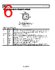
6 / 25 page 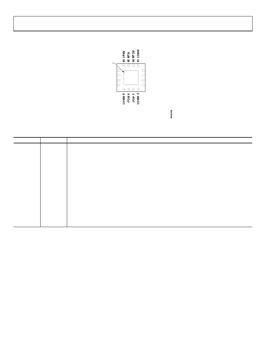 AD8342 Data Sheet Rev. C | Page 6 of 25 PIN CONFIGURATION AND FUNCTION DESCRIPTIONS NOTES 1. CONNECT THE EXPOSED PAD THROUGH A LOW ELECTRICAL AND THERMAL RESISTANCE PATH TO A GROUND PLANE SIMILAR TO THAT SHOWN IN THE EVALUATION BOARD SECTION. 1 VPLO 2 LOCM 3 LOIN 4 COMM 11 PWDN 12 VPDC 10 EXRB 9COMM PIN 1 INDICATOR AD8342 TOP VIEW Figure 2. Pin Configuration Table 4. Pin Function Descriptions Pin No. Mnemonic Description 1 VPLO Positive Supply Voltage for the LO Buffer: 4.75 V to 5.25 V. 2 LOCM AC Ground for Limiting LO Amplifier. This pin is internally biased to VS − 1.6 V. AC couple this pin to ground. 3 LOIN LO Input. Nominal input level: 0 dBm. Input level range: −10 dBm to +4 dBm (relative to 50 Ω). Internally biased to VS − 1.6 V. This pin must be ac-coupled. 4, 5, 8, 9, 13 COMM Device Common (DC Ground). 6, 7 IFOM, IFOP Differential IF Outputs (Open-Collectors). Each requires dc bias of 5.00 V (nominal). 10 EXRB Mixer Bias Voltage. Connect a resistor from EXRB to ground. The typical value of 1.82 kΩ sets the mixer current to nominal value. The minimum resistor value from EXRB to ground = 1.8 kΩ. This pin is internally biased to 1.17 V. 11 PWDN Connect to Ground for Normal Operation. Connect this pin to VS for disable mode. 12 VPDC Positive Supply Voltage for the DC Bias Cell: 4.75 V to 5.25 V. 14 RFCM AC Ground for RF Input. Internally biased to 2.4 V. AC couple this pin to ground. 15 RFIN RF Input. This pin is internally biased to 2.4 V. This pin must be ac-coupled. 16 VPMX Positive Supply Voltage for the Mixer: 4.75 V to 5.25 V. EP Exposed Pad. Connect the exposed pad through a low electrical and thermal resistance path to a ground plane similar to that shown in the Evaluation Board section. See Figure 62 and Figure 63. |
|
|
Link URL |
| Does ALLDATASHEET help your business so far? [ DONATE ] |
About Alldatasheet | Advertisement | Contact us | Privacy Policy | Link to Datasheet | Link Exchange | Manufacturer List All Rights Reserved©Alldatasheet.com |
| Russian : Alldatasheetru.com | Korean : Alldatasheet.co.kr | Spanish : Alldatasheet.es | French : Alldatasheet.fr | Italian : Alldatasheetit.com Portuguese : Alldatasheetpt.com | Polish : Alldatasheet.pl | Vietnamese : Alldatasheet.vn Indian : Alldatasheet.in | Mexican : Alldatasheet.com.mx | British : Alldatasheet.co.uk | New Zealand : Alldatasheet.co.nz |
|
Family Site : ic2ic.com |
icmetro.com |
 Indian ▼
 English
 Chinese
 German
 Japanese
 Russian
 Korean
 Spanish
 French
 Italian
 Portuguese
 Polish
 Vietnamese
 Indian
 Mexican
 British
 New Zealand