|
Electronic Components Datasheet Search |
|
|
Electronic Components Datasheet Search |
|
AD8342ACPZ-R2 Datasheet(PDF) 22 Page - Analog Devices |
|
|
|||||||||||||||||||||||||||||
AD8342ACPZ-R2 Datasheet(HTML) 22 Page - Analog Devices |
|
|
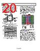
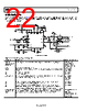
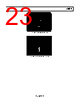
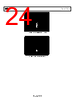
22 / 25 page 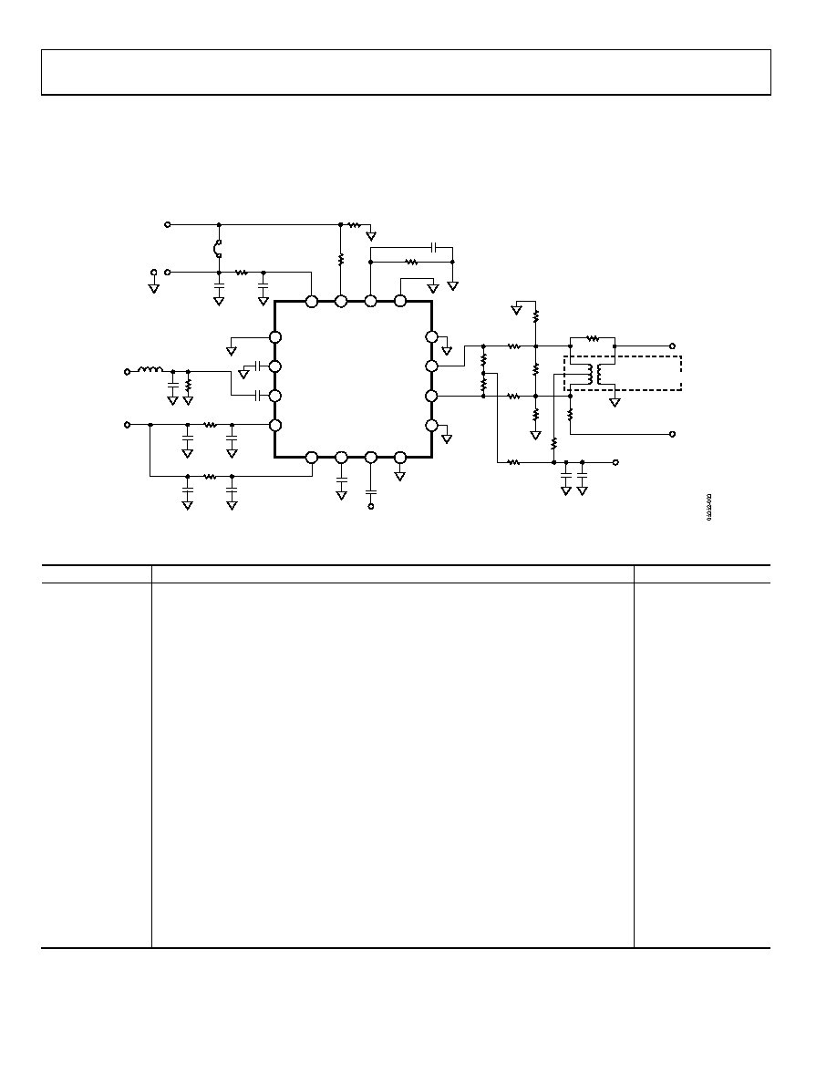 AD8342 Data Sheet Rev. C | Page 22 of 25 EVALUATION BOARD An evaluation board is available for the AD8342. The evaluation board is configured for single-ended signaling at the IF output port via a balun transformer. The schematic for the evaluation board is presented in Figure 61. The representations of the board layout are included in Figure 62 through Figure 65. R2 0Ω R1 0Ω C6 1000pF C4 1000pF C1 1000pF C3 1000pF C5 0.1µF C2 0.1µF VPOS RF_IN C7 1000pF INLO C8 1000pF C9 0.1µF C10 100pF VPOS R11 0Ω R16 0Ω R10 0Ω R12 OPEN Z4 OPEN R4 OPEN 34 16 2 TC2-1T Z2 OPEN R3 OPEN 100Ω TRACES, NO GROUND PLANE IF_OUT+ IF_OUT– R15 0Ω T1 Z1 OPEN Z3 OPEN R5 100Ω C14 OPEN L1 0Ω COMM IFOP IFOM COMM COMM RFCM RFIN VPMX VPDC PWDN EXRB COMM VPLO LOCM LOIN COMM DUT 12 11 10 9 13 14 15 16 1 2 3 4 8 7 6 5 R6 1.82kΩ C11 100pF R7 0Ω C13 100pF C12 0.1µF VPOS GND PWDN VPOS W1 R8 10kΩ R9 0Ω PWDN 50Ω TRACE Figure 61. Evaluation Board Table 7. Evaluation Board Configuration Options Component Description Default Conditions R1, R2, R7, C2, C4, C5, C6, C9, C10, C12, C13 Supply decoupling. Shorts or power supply decoupling resistors and filter capacitors. R1, R2, R7 = 0 Ω C4, C6 = 1000 pF C10, C13 = 100 pF C2, C5, C9, C12 = 0.1 μF R3, R4 Options for a single-ended IF output circuit. R3, R4 = Open R6, C11 RBIAS resistor that sets the bias current for the mixer core. The capacitor provides ac bypass for R6. R6 = 1.82 kΩ C11 = 100 pF R8 Pull down for the PWDN pin. R8 = 10 kΩ R9 Link to the PWDN pin. R9 = 0 Ω C3, R5, C14, L1 RF input. C3 provides a dc block for RF input. R5 provides a resistive input termination. C16 and L1 are provided for reactive matching of the input. C3 = 1000 pF R5 = 100 Ω C14 = Open L1 = 0 Ω C1 RF common ac coupling. Provides a dc block for the RF input common connection. C1 = 1000 pF C8 LO input ac coupling. Provides a dc block for the LO input. C8 = 1000 pF C7 LO common ac coupling. Provides a dc block for the LO input common connection. C7 = 1000 pF W1 Power down. The device is on when the PWDN pin is connected to ground via a 10 kΩ resistor. The device is disabled when PWDN is connected to the positive supply (VS) via W1. T1, R10, R11, R12, R15, R16, Z3, Z4, Z1, Z2, IF output interface. T1 converts a differential high impedance IF output to single-ended. When loaded with 50 Ω, this balun presents a 100 Ω load to the mixers collectors. The center tap of the primary supplies the bias voltage (VS) to the IF output pins. T1 = TC2-1T, 2:1 (Mini- Circuits®) R12 = Open R10, R11, R15, R16 = 0 Ω Z3, Z4 = Open Z1, Z2 = Open |
|
|
Link URL |
| Does ALLDATASHEET help your business so far? [ DONATE ] |
About Alldatasheet | Advertisement | Contact us | Privacy Policy | Link to Datasheet | Link Exchange | Manufacturer List All Rights Reserved©Alldatasheet.com |
| Russian : Alldatasheetru.com | Korean : Alldatasheet.co.kr | Spanish : Alldatasheet.es | French : Alldatasheet.fr | Italian : Alldatasheetit.com Portuguese : Alldatasheetpt.com | Polish : Alldatasheet.pl | Vietnamese : Alldatasheet.vn Indian : Alldatasheet.in | Mexican : Alldatasheet.com.mx | British : Alldatasheet.co.uk | New Zealand : Alldatasheet.co.nz |
|
Family Site : ic2ic.com |
icmetro.com |
 Indian ▼
 English
 Chinese
 German
 Japanese
 Russian
 Korean
 Spanish
 French
 Italian
 Portuguese
 Polish
 Vietnamese
 Indian
 Mexican
 British
 New Zealand