|
Electronic Components Datasheet Search |
|
|
Electronic Components Datasheet Search |
|
LEG Datasheet(PDF) 9 Page - Sensata Technologies, Inc. |
|
|
|||||||||||||||||||||||||||||
LEG Datasheet(HTML) 9 Page - Sensata Technologies, Inc. |
|
|
9 / 26 page 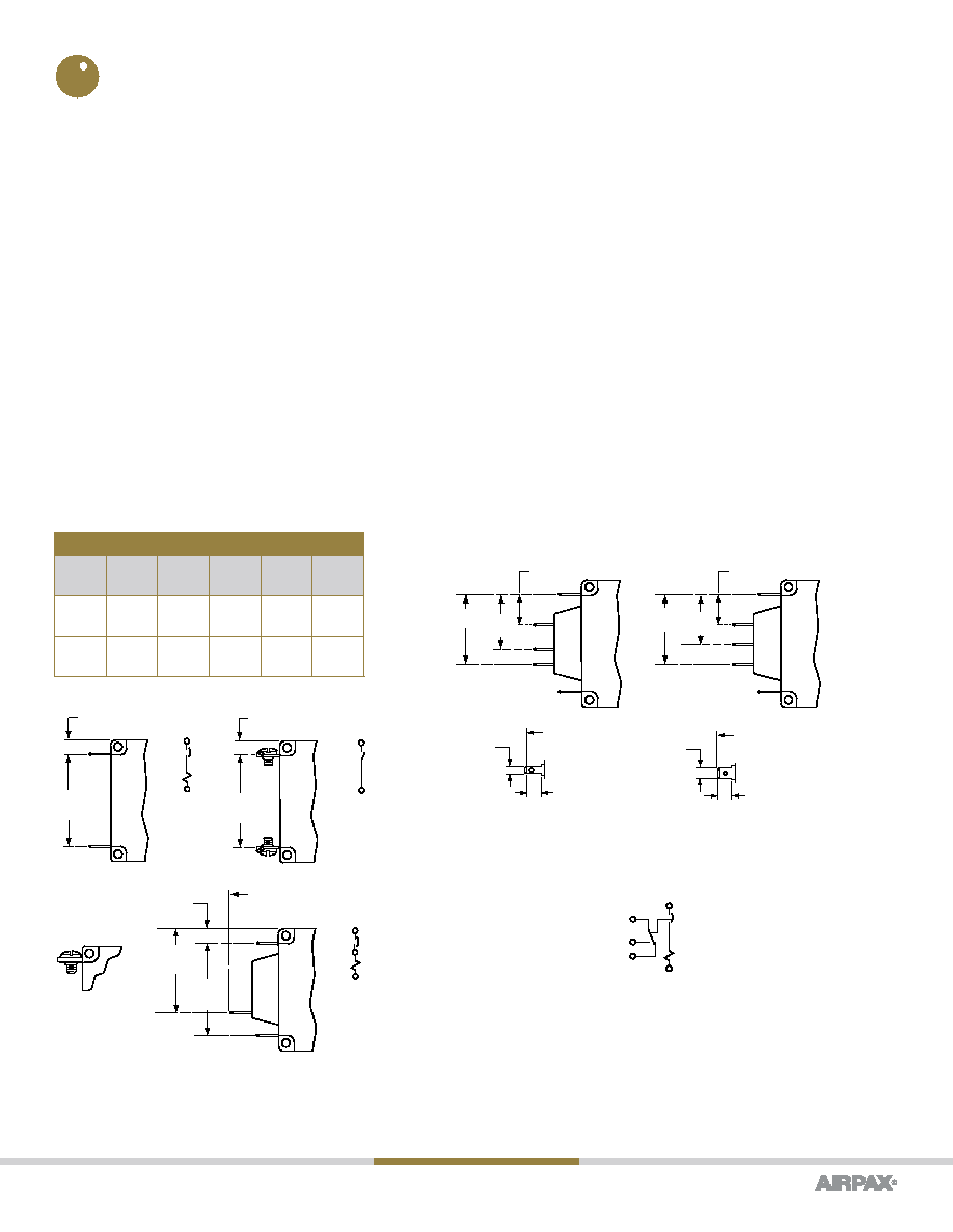 www.sensata.com Page 9 Copyright © 2020 Sensata Technologies, Inc. CONFIGURATIONS Series Trip Shunt Trip Auxiliary Switch (Applies to Series Trip Only) The most popular configuration for magnetic protectors is the series trip where the sensing coil and contacts are in series with the load being protected. The handle position conveniently indicates circuit status. In addition to providing conventional overcurrent protection, it’s simultaneously used as an on-off switch. The shunt trip is designed for controlling two separate loads with one assembly. The control is established by providing overload protection for the critical load. When the current through this load becomes excessive and reaches the trip point, the protector will open and remove power from both loads simultaneously. The total current rating of both loads must not exceed the maximum contact rating. This is furnished as an integral part of a series pole in single or multi-pole assemblies. Isolated electrically from the protector’s circuit, the switch works in unison with the power contacts and provides indication at a remote location of the protector’s on-off status. Auxiliary switch contacts actuate simultaneously with the main protector contacts, and will open regardless of whether the protector contacts are opened manually or electrically. For auxiliary switch ratings below 6Vac or 5Vdc, an auxiliary switch with gold contacts designated as REG is available. Gold contacts are not recommended for load current above 100 milliamps. Note: A: Terminal protrusion dimensions are referenced from back mounting panel. B: Main terminals are male push-on type .250 [6.35] wide x 0.31 [.79] thick x .375 [9.53] long or 8-32 x .187 [4.75] screw type. Metric screw terminals are M4 x 5mm (<=30A): M5 x 5mm screw type (>30A). On TUV approved builds with screw terminals, external tooth lockwashers are supplied. On TUV approved builds with push-on terminals a soldered connection is required above 25 amperes. Main Terminal Types Amp Rating Push- On 8-32 Screw M4 Screw 10-32 Screw M5 Screw .05 to 30 X X X 30.1 to 50 X X 1.530 [38.86] .230 [5.84] 1.530 [38.86] .230 [5.84] 1.530 [38.86] 1.380 [35.05] .230 [5.84] 2.52 MAX. [64.00] (See Note A) Standard Auxiliary Switch Series with Auxiliary Switch .441 [11.20] .848 [21.53] 1.083 [27.51] .469 [11.91] .764 [19.04] 1.059 [26.90] 2.438 MAX. [61.93] (See Note A) .260 [6.60] .110 [2.79] –IREC4 –IREG4 2.454 MAX. [62.33] (See Note A) .250 [6.35] .187 [4.75] –IREC5 C NO NC BREAKER IN OFF POSITION |
|
|
Link URL |
| Does ALLDATASHEET help your business so far? [ DONATE ] |
About Alldatasheet | Advertisement | Contact us | Privacy Policy | Link to Datasheet | Link Exchange | Manufacturer List All Rights Reserved©Alldatasheet.com |
| Russian : Alldatasheetru.com | Korean : Alldatasheet.co.kr | Spanish : Alldatasheet.es | French : Alldatasheet.fr | Italian : Alldatasheetit.com Portuguese : Alldatasheetpt.com | Polish : Alldatasheet.pl | Vietnamese : Alldatasheet.vn Indian : Alldatasheet.in | Mexican : Alldatasheet.com.mx | British : Alldatasheet.co.uk | New Zealand : Alldatasheet.co.nz |
|
Family Site : ic2ic.com |
icmetro.com |
 Indian ▼
 English
 Chinese
 German
 Japanese
 Russian
 Korean
 Spanish
 French
 Italian
 Portuguese
 Polish
 Vietnamese
 Indian
 Mexican
 British
 New Zealand