|
Electronic Components Datasheet Search |
|
|
Electronic Components Datasheet Search |
|
CC1010-RTY1 Datasheet(PDF) 114 Page - Texas Instruments |
|
|
|||||||||||||||||||||||||||||
CC1010-RTY1 Datasheet(HTML) 114 Page - Texas Instruments |
|
|
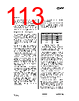
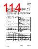
114 / 150 page 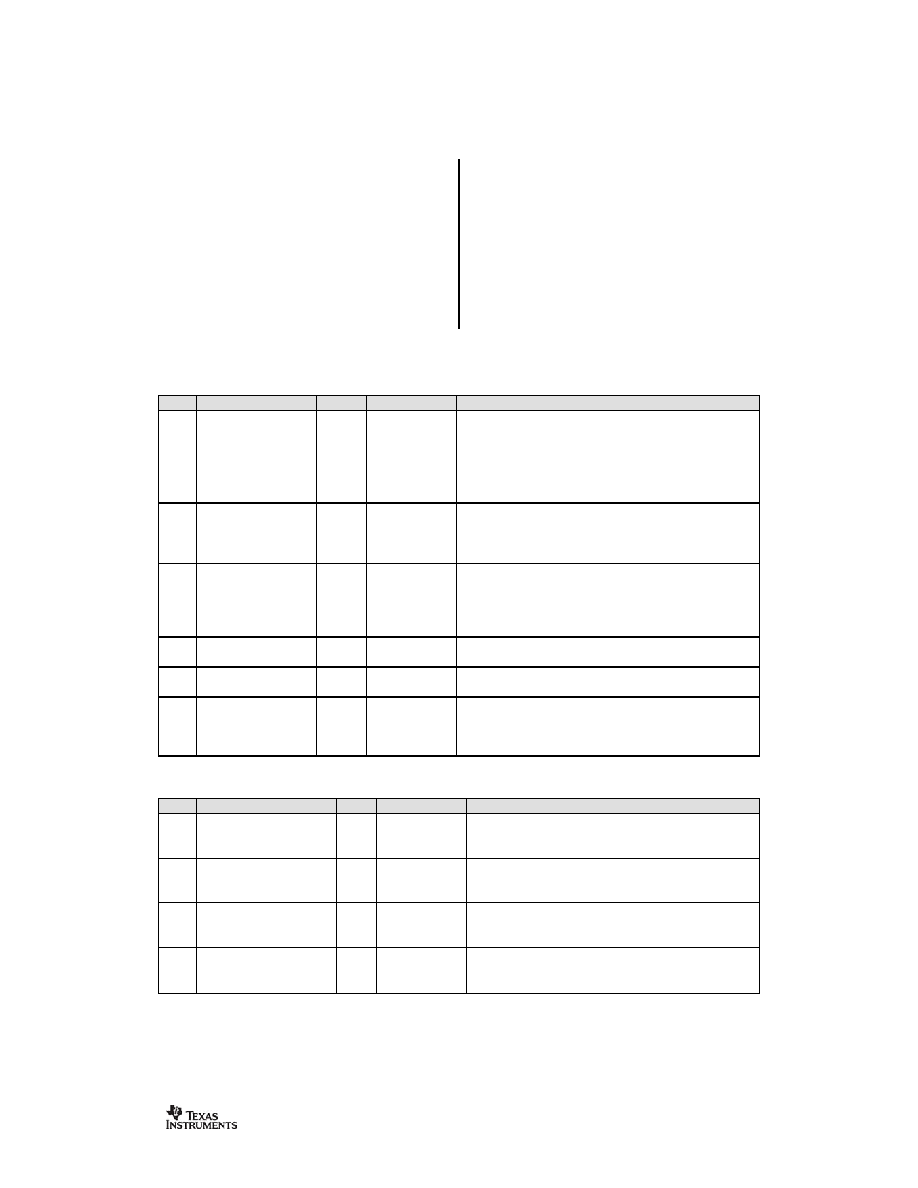 CC1010 SWRS047A Page 114 of 146 the result of the calibration is stored in the TEST0 (VCO capacitance array setting) and TEST2 (Charge pump current setting) registers. The access of these registers depend on the RFMAIN.F_REG bit as there are two physical registers mapped to the same address, one for frequency A and one for frequency B. The calibration result can be read back from TEST0 and TEST2 , and later written back in TEST5.VCO_AO(3:0) and TEST5.CHP_CO(4:0) respectively. TEST5.VCO_OVERRIDE and TEST6.CHP_OVERRIDE must be set in order to make the override values to take effect. The rest of the TESTn registers are not needed for normal operation of CC1010, but are included here for completeness. CAL (0xE5) - PLL Calibration Control Register Bit Name R/W Reset value Description 7 CAL_START R/W 0 ↑ 1 : Calibration started 0 : Calibration inactive Calibration is started after a positive transition on CAL_START . CAL_START must manually be written to 0 after calibration is complete (read the CAL_COMPLETE flag) 6 CAL_DUAL R/W 0 1 : Store calibration in both A and B (dual calibration) 0 : Store calibration in A or B defined by RFMAIN.F_REG 5 CAL_WAIT R/W 0 1 : Normal Calibration Wait Time (Recommended) 0 : Half Calibration Wait Time The calibration time is proportional to the internal reference frequency fREF. See the main text. 4 CAL_CURRENT R/W 0 1 : Calibration Current Doubled 0 : Normal Calibration Current (Recommended) 3 CAL_COMPLETE R 0 Status bit which is set when the calibration is complete 2:0 CAL_ITERATE R/W 101 Iteration start value for calibration DAC 000 - 101: Not used 110 : Normal start value 111 : Not used TEST6 (0xFF) – PLL Test Register 6 Bit Name R/W Reset value Description 7 LOOPFILTER_TP1 R/W 0 Testpoint 1 select 0 : CHP_OUT tied to GND 1 : Select testpoint 1 to CHP_OUT 6 LOOPFILTER_TP2 R/W 0 Testpoint 2 select 0 : CHP_OUT tied to GND 1 : Select testpoint 2 to CHP_OUT 5 CHP_OVERRIDE R/W 0 Charge pump current override enable 0 : use calibrated value. Used in RX mode 1 : use CHP_CO[4:0] value. Used in TX mode 4:0 CHP_CO(4:0) R/W 0x10 Charge pump current DAC override value, applied when CHP_OVERRIDE is high. Use 0x1B in TX mode. |
|
Link URL |
| Does ALLDATASHEET help your business so far? [ DONATE ] |
About Alldatasheet | Advertisement | Contact us | Privacy Policy | Link to Datasheet | Link Exchange | Manufacturer List All Rights Reserved©Alldatasheet.com |
| Russian : Alldatasheetru.com | Korean : Alldatasheet.co.kr | Spanish : Alldatasheet.es | French : Alldatasheet.fr | Italian : Alldatasheetit.com Portuguese : Alldatasheetpt.com | Polish : Alldatasheet.pl | Vietnamese : Alldatasheet.vn Indian : Alldatasheet.in | Mexican : Alldatasheet.com.mx | British : Alldatasheet.co.uk | New Zealand : Alldatasheet.co.nz |
|
Family Site : ic2ic.com |
icmetro.com |
 Indian ▼
 English
 Chinese
 German
 Japanese
 Russian
 Korean
 Spanish
 French
 Italian
 Portuguese
 Polish
 Vietnamese
 Indian
 Mexican
 British
 New Zealand