 |
Electronic Components Datasheet Search |
|
|
Electronic Components Datasheet Search |
|
EM357-RTR Datasheet(PDF) 143 Page - List of Unclassifed Manufacturers |
|
|
|||||||||||||||||||||||||||||
EM357-RTR Datasheet(HTML) 143 Page - List of Unclassifed Manufacturers |
|
|
143 / 240 page 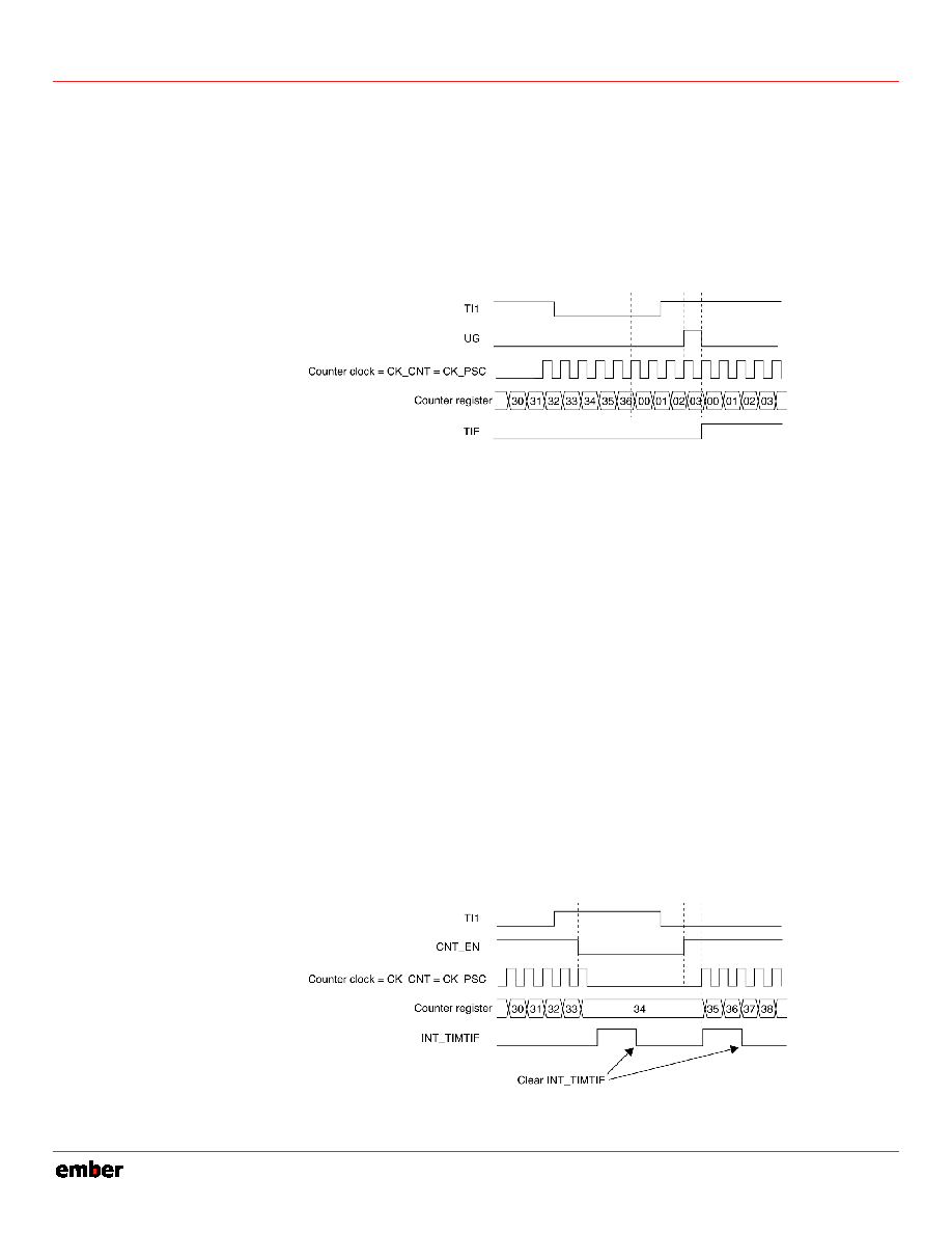 EM351 / EM357 The counter starts counting on the internal clock, then behaves normally until the TI1 rising edge. When TI1 rises, the counter is cleared and restarts from 0. In the meantime, the trigger flag is set (the INT_TIMTIF bit in the INT_TIMxFLAG register) and an interrupt request can be sent if enabled (depending on the INT_TIMTIF bit in the INT_TIMxCFG register). Figure 9-27 shows this behavior when the auto-reload register TIMx_ARR = 0x36. The delay between the rising edge on TI1 and the actual reset of the counter is due to the resynchronization circuit on the TI1 input. Figure 9-27. Control Circuit in Reset Mode 9.3.13.2 Slave Mode: Gated Mode In gated mode the counter is enabled depending on the level of a selected input. In the following example, the up-counter counts only when the TI1 input is low: Configure channel 1 to detect low levels on TI1: • Configure the input filter duration. In this example, no filter is required, so TIM_IC1F = 0000. • The capture prescaler is not used for triggering, so it is not configured. • The TIM_CC1S bits select the input capture source only, TIM_CC1S = 01 in the TIMx_CCMR1 register. • Write TIM_CC1P = 1 in the TIMx_CCER register to validate the polarity (and detect low level only). Configure the timer in gated mode: Write TIM_SMS = 101 in the TIMx_SMCR register. Select TI1 as the input source by writing TIM_TS = 101 in the TIMx_SMCR register. Enable the counter: Write TIM_CEN = 1 in the TIMx_CR1 register. In gated mode, the counter does not start if TIM_CEN = 0, regardless of the trigger input level. The counter starts counting on the internal clock as long as TI1 is low and stops as soon as TI1 becomes high. The INT_TIMTIF flag in the INT_TIMxFLAG register is set when the counter starts and when it stops. The delay between the rising edge on TI1 and the actual stop of the counter is due to the resynchronization circuit on the TI1 input. Figure 9-28 shows the counter in gated mode with counting enabled when TI1 is low. Figure 9-28. Control Circuit in Gated Mode 9-23 120-035X-000D Preliminary |
|
Link URL |
| Does ALLDATASHEET help your business so far? [ DONATE ] |
About Alldatasheet | Advertisement | Contact us | Privacy Policy | Link to Datasheet | Link Exchange | Manufacturer List All Rights Reserved©Alldatasheet.com |
| Russian : Alldatasheetru.com | Korean : Alldatasheet.co.kr | Spanish : Alldatasheet.es | French : Alldatasheet.fr | Italian : Alldatasheetit.com Portuguese : Alldatasheetpt.com | Polish : Alldatasheet.pl | Vietnamese : Alldatasheet.vn Indian : Alldatasheet.in | Mexican : Alldatasheet.com.mx | British : Alldatasheet.co.uk | New Zealand : Alldatasheet.co.nz |
|
Family Site : ic2ic.com |
icmetro.com |
 Indian ▼
 English
 Chinese
 German
 Japanese
 Russian
 Korean
 Spanish
 French
 Italian
 Portuguese
 Polish
 Vietnamese
 Indian
 Mexican
 British
 New Zealand


