 |
Electronic Components Datasheet Search |
|
|
Electronic Components Datasheet Search |
|
EM357-RTR Datasheet(PDF) 151 Page - List of Unclassifed Manufacturers |
|
|
|||||||||||||||||||||||||||||
EM357-RTR Datasheet(HTML) 151 Page - List of Unclassifed Manufacturers |
|
|
151 / 240 page 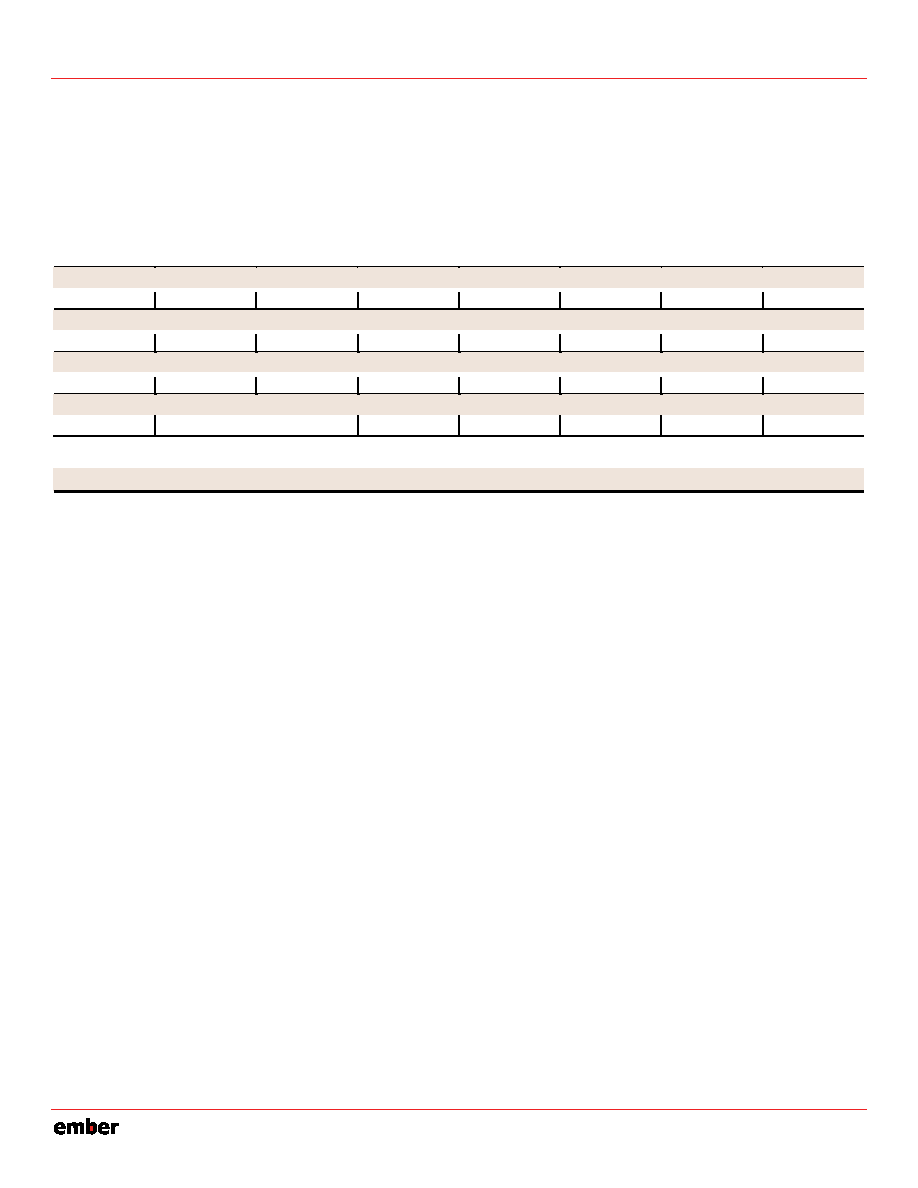 EM351 / EM357 9-31 120-035X-000D Preliminary 9.5 Registers TIMx_CR1 TIM1_CR1 Timer 1 Control Register 1 Address: 0x4000E000 Reset: 0x0 TIM2_CR1 Timer 2 Control Register 1 Address: 0x4000F000 Reset: 0x0 31 30 29 28 27 26 25 24 0 0 0 0 0 0 0 0 23 22 21 20 19 18 17 16 0 0 0 0 0 0 0 0 15 14 13 12 11 10 9 8 0 0 0 0 0 0 0 0 7 6 5 4 3 2 1 0 TIM_ARBE TIM_CMS TIM_DIR TIM_OPM TIM_URS TIM_UDIS TIM_CEN Bitname Bitfield Access Description TIM_ARBE [7] RW Auto-Reload Buffer Enable. 0: TIMx_ARR register is not buffered. 1: TIMx_ARR register is buffered. TIM_CMS [6:5] RW Center-aligned Mode Selection. 00: Edge-aligned mode. The counter counts up or down depending on the direction bit (TIM_DIR). 01: Center-aligned mode 1. The counter counts up and down alternatively. Output compare interrupt flags of configured output channels (TIM_CCyS=00 in TIMx_CCMRy register) are set only when the counter is counting down. 10: Center-aligned mode 2. The counter counts up and down alternatively. Output compare interrupt flags of configured output channels (TIM_CCyS=00 in TIMx_CCMRy register) are set only when the counter is counting up. 11: Center-aligned mode 3. The counter counts up and down alternatively. Output compare interrupt flags of configured output channels (TIM_CCyS=00 in TIMx_CCMRy register) are set both when the counter is counting up or down. Note: Software may not switch from edge-aligned mode to center-aligned mode when the counter is enabled (TIM_CEN=1). TIM_DIR [4] RW Direction. 0: Counter used as up-counter. 1: Counter used as down-counter. TIM_OPM [3] RW One Pulse Mode. 0: Counter does not stop counting at the next UEV. 1: Counter stops counting at the next UEV (and clears the bit TIM_CEN). TIM_URS [2] RW Update Request Source. 0: When enabled, update interrupt requests are sent as soon as registers are updated (counter overflow/underflow, setting the TIM_UG bit, or update generation through the slave mode controller). 1: When enabled, update interrupt requests are sent only when the counter reaches overflow or underflow. TIM_UDIS [1] RW Update Disable. 0: A UEV is generated as soon as a counter overflow occurs, a software update is generated, or a hardware reset is generated by the slave mode controller. Shadow registers are then loaded with their buffer register values. 1: A UEV is not generated and shadow registers keep their value (TIMx_ARR, TIMx_PSC, TIMx_CCRy). The counter and the prescaler are reinitialized if the TIM_UG bit is set or if a hardware reset is received from the slave mode controller. |
|
Link URL |
| Does ALLDATASHEET help your business so far? [ DONATE ] |
About Alldatasheet | Advertisement | Contact us | Privacy Policy | Link to Datasheet | Link Exchange | Manufacturer List All Rights Reserved©Alldatasheet.com |
| Russian : Alldatasheetru.com | Korean : Alldatasheet.co.kr | Spanish : Alldatasheet.es | French : Alldatasheet.fr | Italian : Alldatasheetit.com Portuguese : Alldatasheetpt.com | Polish : Alldatasheet.pl | Vietnamese : Alldatasheet.vn Indian : Alldatasheet.in | Mexican : Alldatasheet.com.mx | British : Alldatasheet.co.uk | New Zealand : Alldatasheet.co.nz |
|
Family Site : ic2ic.com |
icmetro.com |
 Indian ▼
 English
 Chinese
 German
 Japanese
 Russian
 Korean
 Spanish
 French
 Italian
 Portuguese
 Polish
 Vietnamese
 Indian
 Mexican
 British
 New Zealand


