|
Electronic Components Datasheet Search |
|
|
Electronic Components Datasheet Search |
|
AS3661 Datasheet(PDF) 24 Page - ams AG |
|
|
|||||||||||||||||||||||||||||
AS3661 Datasheet(HTML) 24 Page - ams AG |
|
|
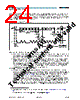
24 / 87 page  www.austriamicrosystems.com Revision 1.3 23 - 85 AS3661 Datasheet - D e t a i l e d D e s c r i p t i o n A device that acknowledges must pull down the SDA line during the acknowledge clock pulse in such a way that the SDA line is stable LOW during the HIGH period of the acknowledge-related clock pulse. Of course, setup and hold times must be taken into account. A master must signal an end of data to the slave by not generating an acknowledge bit on the last byte that has been clocked out of the slave. In this case, the slave must leave the data line HIGH to enable the master to generate the STOP condition. Figure 25. Data Transfer on I 2C Serial Bus Depending upon the state of the R/W bit, two types of data transfer are possible: 1. Data transfer from a master transmitter to a slave receiver. The first byte transmitted by the master is the slave address. Next follows a number of data bytes. The slave returns an acknowledge bit after each received byte. Data is transferred with the most significant bit (MSB) first. 2. Data transfer from a slave transmitter to a master receiver. The master transmits the first byte (the slave address). The slave then returns an acknowledge bit, followed by the slave transmitting a number of data bytes. The master returns an acknowledge bit after all received bytes other than the last byte. At the end of the last received byte, a “not acknowledge” is returned. The master device generates all of the serial clock pulses and the START and STOP conditions. A transfer is ended with a STOP condition or with a repeated START condition. Since a repeated START condition is also the beginning of the next serial transfer, the bus is not released. Data is transferred with the most significant bit (MSB) first. The AS3661 can operate in the following two modes: 1. Slave Receiver Mode (Write Mode): Serial data and clock are received through SDA and SCL. After each byte is received an acknowledge bit is transmitted. START and STOP conditions are recognized as the begin- ning and end of a serial transfer. Address recognition is performed by hardware after reception of the slave address and direction bit (see Figure 26). The slave address byte is the first byte received after the master generates the START condition. The slave address byte contains the 7-bit AS3661 address, which is 0110010 2 , followed by the direction bit (R/W), which, for a write, is 0. 3 After receiving and decoding the slave address byte the device outputs an acknowledge on the SDA line. After the AS3661 acknowledges the slave address + write bit, the master transmits a register address to the AS3661. This sets the register pointer on the AS3661. The master may then transmit zero or more bytes of data (if more than one data byte is written see also Blockwrite/read boundaries on page 24), with the AS3661 acknowledging each byte received. The 2. ’XXX’ depends on the external connection of ASEL0 and ASEL1; see Chip Address Configuration on page 22 3. The address for writing to the AS3661 is 8Xh = 01100100b - see Table 5 SLAVE ADDRESS ACKNOWLEDGEMENT SIGNAL FROM RECEIVER ACKNOWLEDGEMENT SIGNAL FROM RECEIVER REPEATED IF MORE BYTES ARE TRANSFERRED STOP CONDITION OR REPEATED START CONDITION START CONDITION SCL SDA MSB R/W DIRECTION BIT ACK 1 2 6 7 8 9 1 2 3-8 8 9 |
|
Link URL |
| Does ALLDATASHEET help your business so far? [ DONATE ] |
About Alldatasheet | Advertisement | Contact us | Privacy Policy | Link to Datasheet | Link Exchange | Manufacturer List All Rights Reserved©Alldatasheet.com |
| Russian : Alldatasheetru.com | Korean : Alldatasheet.co.kr | Spanish : Alldatasheet.es | French : Alldatasheet.fr | Italian : Alldatasheetit.com Portuguese : Alldatasheetpt.com | Polish : Alldatasheet.pl | Vietnamese : Alldatasheet.vn Indian : Alldatasheet.in | Mexican : Alldatasheet.com.mx | British : Alldatasheet.co.uk | New Zealand : Alldatasheet.co.nz |
|
Family Site : ic2ic.com |
icmetro.com |
 Indian ▼
 English
 Chinese
 German
 Japanese
 Russian
 Korean
 Spanish
 French
 Italian
 Portuguese
 Polish
 Vietnamese
 Indian
 Mexican
 British
 New Zealand