|
Electronic Components Datasheet Search |
|
|
Electronic Components Datasheet Search |
|
EM342-RTR Datasheet(PDF) 51 Page - Silicon Laboratories |
|
|
|||||||||||||||||||||||||||||
EM342-RTR Datasheet(HTML) 51 Page - Silicon Laboratories |
|
|
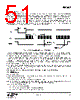
51 / 143 page 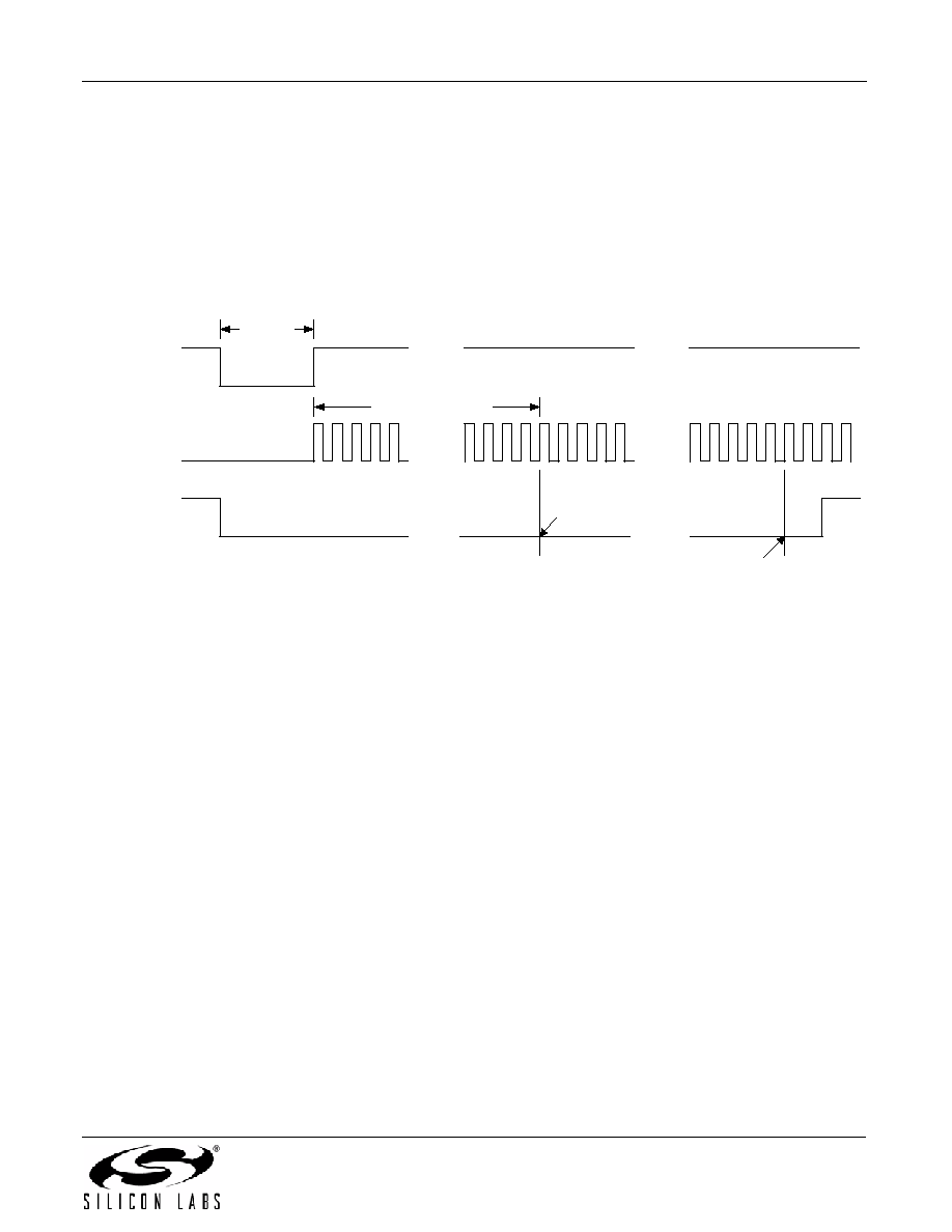 EM342 Rev 1.0 51 7.5. Boot Configuration nBOOTMODE is a special alternate function of PA5 that is active only during a pin reset (nRESET) or a power-on- reset of the always-powered domain (POR HV). If nBOOTMODE is asserted (pulled or driven low) when coming out of reset, the processor starts executing an embedded serial-link-only monitor instead of its normal program. While in reset and during the subsequent power-on-reset startup delay (512 OSCHF clocks), PA5 is automatically configured as an input with a pull-up resistor. At the end of this time, the EM342 samples nBOOTMODE: a high level selects normal boot mode, and a low level selects the embedded monitor. Figure 7.2 shows the timing parameters for invoking monitor mode from a pin (nRESET) reset. Because OSCHF is running uncalibrated during the reset sequence, the time for 512 OSCHF clocks may vary as indicated. Figure 7.2. nBOOTMODE and nRESET Timing Timing for a power-on-reset is similar except that OSCHF does not begin oscillating until up to 70 µsec after both core and HV supplies are valid. Combined with the maximum 250 µsec allowed for HV to ramp from 0.5 V to 1.7 V, an additional 320 µsec may be added to the 512 OSCHF clocks until nBOOTMODE is sampled. If the monitor mode is selected (nBOOTMODE is low after 512 clocks), the FIB monitor software begins execution. In order to filter out inadvertent jumps into the monitor, the FIB monitor re-samples the nBOOTMODE signal after a 3 ms delay. If the signal is still low, then the device stays in monitor mode. If the signal is high, then monitor mode is exited and the normal program begins execution. In summary, the nBOOTMODE signal must be held low for 4 ms in order to properly invoke the FIB monitor. After nBOOTMODE has been sampled, PA5 is configured as a floating input like the other GPIO configurations. The GPIO_BOOTMODE bit in the GPIO_DBGSTAT register captures the state of nBOOTMODE so that software may act on this signal if required. Note: To avoid inadvertently asserting nBOOTMODE, PA5’s capacitive load may not exceed 250 pF. 7.6. GPIO Modes 7.6.1. Analog Mode Analog mode enables analog functions, and disconnects a pin from the digital input and output logic. Only the following GPIO pins have analog functions: PC6 and PC7 can connect to an optional 32.768 kHz crystal. Note: When an external timing source is required, a 32.768 kHz crystal is commonly connected to PC6 and PC7. Alternatively, when PC7 is configured as a digital input, PC7 can accept a digital external clock input. When configured in analog mode: The output drivers are disabled. The internal pull-up and pull-down resistors are disabled. The Schmitt trigger input is connected to a high logic level. . . . nRESET OSCHF . . . . . . nBOOTMODE 26 µsec min . . . . . . . . . 512 clocks; 26 µsec min – 85 µsec max nBOOTMODE Sampled; FIB Monitor mode entered nBOOTMODE Sampled by FIB Monitor code |
|
Link URL |
| Does ALLDATASHEET help your business so far? [ DONATE ] |
About Alldatasheet | Advertisement | Contact us | Privacy Policy | Link to Datasheet | Link Exchange | Manufacturer List All Rights Reserved©Alldatasheet.com |
| Russian : Alldatasheetru.com | Korean : Alldatasheet.co.kr | Spanish : Alldatasheet.es | French : Alldatasheet.fr | Italian : Alldatasheetit.com Portuguese : Alldatasheetpt.com | Polish : Alldatasheet.pl | Vietnamese : Alldatasheet.vn Indian : Alldatasheet.in | Mexican : Alldatasheet.com.mx | British : Alldatasheet.co.uk | New Zealand : Alldatasheet.co.nz |
|
Family Site : ic2ic.com |
icmetro.com |
 Indian ▼
 English
 Chinese
 German
 Japanese
 Russian
 Korean
 Spanish
 French
 Italian
 Portuguese
 Polish
 Vietnamese
 Indian
 Mexican
 British
 New Zealand