|
Electronic Components Datasheet Search |
|
|
Electronic Components Datasheet Search |
|
EM342-RTR Datasheet(PDF) 34 Page - Silicon Laboratories |
|
|
|||||||||||||||||||||||||||||
EM342-RTR Datasheet(HTML) 34 Page - Silicon Laboratories |
|
|
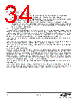
34 / 143 page  EM342 34 Rev 1.0 6.1. Power Domains The EM342 contains three power domains: An “always-on domain” containing all logic and analog cells required to manage the EM342’s power modes, including the GPIO controller and sleep timer. This domain must remain powered. A “core domain” containing the CPU, Nested Vectored Interrupt Controller (NVIC), and peripherals. To save power, this domain can be powered down using a mode called deep sleep. A “memory domain” containing the RAM and flash memories. This domain is managed by the power management controller. When in deep sleep, the RAM portion of this domain is powered from the always- on domain supply to retain the RAM contents while the regulators are disabled. During deep sleep the flash portion is completely powered down. 6.1.1. Internally Regulated Power The preferred and recommended power configuration is to use the internal regulated power supplies to provide power to the core and memory domains. The internal regulators (VREG_1V25 and VREG_1V8) generate nominal 1.25 and 1.8 V supplies. The 1.25 V supply is internally routed to the core domain and to an external pin. The 1.8 V supply is routed to an external pin where it can be externally routed back into the chip to supply the memory domain. The internal regulators are described in "14. Integrated Voltage Regulator" on page 117. When using the internal regulators, the always-on domain must be powered between 2.1 and 3.6 V at all four VDD_PADS pins. When using the internal regulators, the VREG_1V8 regulator output pin (VREG_OUT) must be connected to the VDD_MEM, VDD_PADSA, VDD_VCO, VDD_RF, VDD_IF, VDD_PRE, and VDD_SYNTH pins. When using the internal regulators, the VREG_1V25 regulator output and supply requires a connection between both VDD_CORE pins. 6.1.2. Externally Regulated Power Optionally, the on-chip regulators may be left unused, and the core and memory domains may instead be powered from external supplies. For simplicity, the voltage for the core domain can be raised to nominal 1.8 V, requiring only one external regulator, or the core domain can be powered from the on-chip regulators while the other domains are powered externally. Note that if the core domain is powered at a higher voltage (1.8 V instead of 1.25 V) then power consumption increases. A regulator enable signal, REG_EN, is provided for control of external regulators. This is an open-drain signal that requires an external pull-up resistor. If REG_EN is not required to control external regulators it can be disabled (see "7.3. Forced Functions" on page 50). Using an external regulator requires the always-on domain to be powered between 2.1 and 3.6 V at all four VDD_PADS pins. When using an external regulator, the VREG_1V8 regulator output pin (VREG_OUT) must be left unconnected. When using an external regulator, this external nominal 1.8 V supply has to be connected to both VDD_CORE pins and to the VDD_MEM, VDD_PADSA, VDD_VCO, VDD_RF, VDD_IF, VDD_PRE and VDD_SYNTH pins. |
|
Link URL |
| Does ALLDATASHEET help your business so far? [ DONATE ] |
About Alldatasheet | Advertisement | Contact us | Privacy Policy | Link to Datasheet | Link Exchange | Manufacturer List All Rights Reserved©Alldatasheet.com |
| Russian : Alldatasheetru.com | Korean : Alldatasheet.co.kr | Spanish : Alldatasheet.es | French : Alldatasheet.fr | Italian : Alldatasheetit.com Portuguese : Alldatasheetpt.com | Polish : Alldatasheet.pl | Vietnamese : Alldatasheet.vn Indian : Alldatasheet.in | Mexican : Alldatasheet.com.mx | British : Alldatasheet.co.uk | New Zealand : Alldatasheet.co.nz |
|
Family Site : ic2ic.com |
icmetro.com |
 Indian ▼
 English
 Chinese
 German
 Japanese
 Russian
 Korean
 Spanish
 French
 Italian
 Portuguese
 Polish
 Vietnamese
 Indian
 Mexican
 British
 New Zealand