|
Electronic Components Datasheet Search |
|
|
Electronic Components Datasheet Search |
|
EM342-RTR Datasheet(PDF) 78 Page - Silicon Laboratories |
|
|
|||||||||||||||||||||||||||||
EM342-RTR Datasheet(HTML) 78 Page - Silicon Laboratories |
|
|
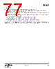
78 / 143 page 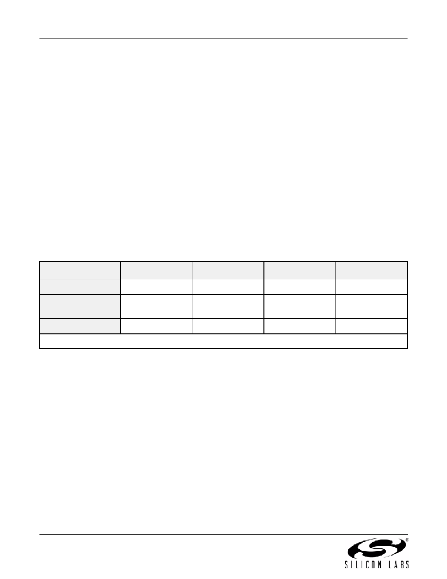 EM342 78 Rev 1.0 8.4. UART—Universal Asynchronous Receiver/Transmitter The SC1 UART is enabled by writing 1 to SC1_MODE. The UART supports the following features: Flexible baud rate clock (300 bps to 921.6 kbps) Data bits (7 or 8) Parity bits (none, odd, or even) Stop bits (1 or 2) False start bit and noise filtering Receive and transmit FIFOs Optional RTS/CTS flow control Receive and transmit DMA channels 8.4.1. GPIO Usage The UART uses two signals to transmit and receive serial data: TXD (Transmitted Data) - serial data sent by the EM342 RXD (Received Data) - serial data received by the EM342 If RTS/CTS flow control is enabled, these two signals are also used: nRTS (Request To Send) - indicates the EM342 is able to receive data nCTS (Clear To Send) - inhibits sending data from the EM342 if not asserted The GPIO pins assigned to these signals are shown in Table 8.4. Table 8.4. UART GPIO Usage TXD RXD nCTS1 nRTS* Direction Output Input Input Output GPIO Configuration Alternate Output (push-pull) Input Input Alternate Output (push-pull) SC1 pin PB1 PB2 PB3 PB4 *Note: Only used if RTS/CTS hardware flow control is enabled. |
|
Link URL |
| Does ALLDATASHEET help your business so far? [ DONATE ] |
About Alldatasheet | Advertisement | Contact us | Privacy Policy | Link to Datasheet | Link Exchange | Manufacturer List All Rights Reserved©Alldatasheet.com |
| Russian : Alldatasheetru.com | Korean : Alldatasheet.co.kr | Spanish : Alldatasheet.es | French : Alldatasheet.fr | Italian : Alldatasheetit.com Portuguese : Alldatasheetpt.com | Polish : Alldatasheet.pl | Vietnamese : Alldatasheet.vn Indian : Alldatasheet.in | Mexican : Alldatasheet.com.mx | British : Alldatasheet.co.uk | New Zealand : Alldatasheet.co.nz |
|
Family Site : ic2ic.com |
icmetro.com |
 Indian ▼
 English
 Chinese
 German
 Japanese
 Russian
 Korean
 Spanish
 French
 Italian
 Portuguese
 Polish
 Vietnamese
 Indian
 Mexican
 British
 New Zealand