 |
Electronic Components Datasheet Search |
|
|
Electronic Components Datasheet Search |
|
KMA310 Datasheet(PDF) 21 Page - NXP Semiconductors |
|
|
|||||||||||||||||||||||||||||
KMA310 Datasheet(HTML) 21 Page - NXP Semiconductors |
|
|
21 / 71 page 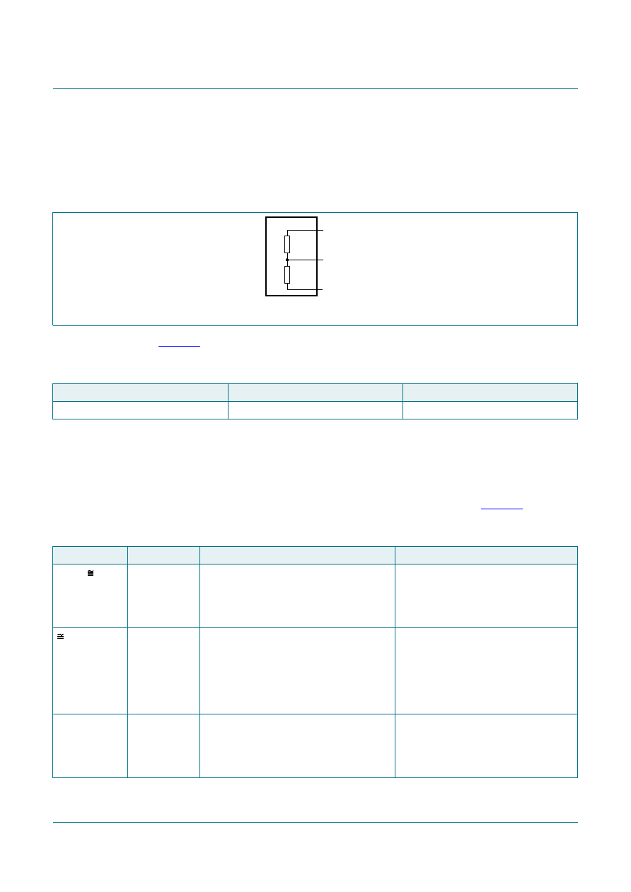 NXP Semiconductors KMA310 Programmable angle sensor IC KMA310 All information provided in this document is subject to legal disclaimers. © NXP B.V. 2019. All rights reserved. Product data sheet Rev. 3 — 27 February 2019 21 / 71 10.2 Power-loss detection (SM-18) and GND-loss detection (SM-19) The power-loss detection circuit enables the detection of an interrupted supply or ground line of the mixed signal IC. If there is a power-loss condition, two internal switches in the sensor are closed, connecting the pin of the analog output to the supply voltage and the ground pin. aaa-028523 ZO(pl) ZO(pl) OUT/DATA GND VDD OUTPUT Figure 12. Equivalent output circuit in a power-loss condition Table 32 describes the power-loss behavior and gives the resulting output voltage depending on the interrupted supply or ground line and the load resistance. Table 32. Power-loss behavior Load resistance Interrupted supply line Interrupted ground line RL(ext) > 5 kΩ VO ≤ 4 %VDD VO ≥ 96 %VDD 10.3 Supply overvoltage detection (SM-16) and undervoltage detection (SM-17) If the supply voltage is below the switch-off threshold voltage, a status bit is set and the output goes into diagnostic mode. If the supply voltage is above the overvoltage switch-on threshold voltage, the output switches to diagnostic mode. Table 33 describes the system behavior depending on the voltage range of the supply voltage. Table 33. System behavior for each output mode Supply voltage State Analog mode SENT mode 0 V to 1.8 V startup power The output buffer drives an active LOW or is powered down, but the switches of the power-loss detection circuit are not fully opened and set the output to a level between ground and half the supply voltage. high-ohmic output stage; external pull-up resistor defines output voltage 1.8 V to VPOR power-on reset The power-loss charge pump is fully operational and turns the switches of the detection circuit off. The output buffer drives an active LOW and sets the output to the lower diagnostic level. During the reset phase, all circuits are in reset and/or power-down mode. The output buffer drives an active LOW. During the reset phase, all circuits are in reset and/or power-down mode. VPOR to Vth(on) or Vth(off) initialization The digital core and the oscillator are active. After reset, the content of the non-volatile memory is copied into the shadow registers. The output buffer drives an active LOW. The digital core and the oscillator are active. After reset, the content of the non-volatile memory is copied into the shadow registers. The output buffer drives an active LOW. |
|
Link URL |
| Does ALLDATASHEET help your business so far? [ DONATE ] |
About Alldatasheet | Advertisement | Contact us | Privacy Policy | Link to Datasheet | Link Exchange | Manufacturer List All Rights Reserved©Alldatasheet.com |
| Russian : Alldatasheetru.com | Korean : Alldatasheet.co.kr | Spanish : Alldatasheet.es | French : Alldatasheet.fr | Italian : Alldatasheetit.com Portuguese : Alldatasheetpt.com | Polish : Alldatasheet.pl | Vietnamese : Alldatasheet.vn Indian : Alldatasheet.in | Mexican : Alldatasheet.com.mx | British : Alldatasheet.co.uk | New Zealand : Alldatasheet.co.nz |
|
Family Site : ic2ic.com |
icmetro.com |
 Indian ▼
 English
 Chinese
 German
 Japanese
 Russian
 Korean
 Spanish
 French
 Italian
 Portuguese
 Polish
 Vietnamese
 Indian
 Mexican
 British
 New Zealand


